 |
Double Barrel
Switching™ |
This modification will alter the appearance of your guitar. |
Back in 2001 I had an idea for a modification that I felt might be a real winner. I drew
up the schematic but between surgery and a much heavier workload at the paying job I never got a chance
to protoype it. In January of 2004 I finally prototyped it.
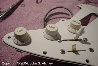
This modification adds a second five-position switch and removes one of the tone controls (the
middle tone knob in the picture above is actually glued on, there is no pot behind it).
The added switch is a four-pole, five-position "super switch." Other than the (for this
site) standard wiring and shielding materials – including an isolation capacitor for safety --
read the "Quieting the Beast" modification – that is the only new part you will
need to buy.
The super switch is used to provide four very useful new pickup combinations. In the remaining
position the super switch passes the signals on to the standard five way switch that gives all
of the standard Stratocaster-style combinations. Working from neckward towards the
bridge or heel the new switch gives the following combinations:
- Pass through to standard switch.
- Neck and bridge in parallel.
- Middle and bridge in series.
- Neck and bridge in series.
- Neck and bridge in series and out of phase.
The reason I was so excited about this modification is that it provides all of the positions
that I've found most useful from my previous modifications without sacrificing any of the
standard positions and without using a whole carton of switches. It has fully lived up to my
expectations.
Prototyping this modification also seems to have confirmed another trend I'd been noticing.
It seems that weak, "underwound" pickups respond much better to changes in the way they are
wired than do very strong "overwound" pickups. This is especially true of the out-of-phase
series position which is rather ho-hum with hot Rio Grande humbuckers but decent with Fralin single
coils, very good with some very tasty but moderately weak Duncan licensed copies, and absolutely
superb with the very weak stacked humbuckers (Bartolini 3XV "vintage") I used in this prototype.
These Bartolini pickups have weak magnets and "underwound" coils (only about 4.3k DC resistance per
pickup). They are really intended to be used with a preamp though I have used them quite
happily without.
So, if you want the widest variety of tones at your fingertips the answer may be to
forget those ultra-hot humbuckers and such – and instead go with some fairly wimpy pickups and use a
preamp or a stompbox to boost the signal.
Please note that the wiring diagram below shows one possible layout for this modification.
Note that it will not match the photographs exactly because I moved things around slightly when
I built the prototype. (I discovered that I'd used the concentric pot I'd ordered months ago for this
modification in the preamp for my bass.)
When I drew up the schematic I did not think that there would be room for two full-sized
standard pots but when I started working on the prototype I found that they will fit fine.
I actually prefer the layout as built as it avoids using a concentric pot and leaves plenty
of room in just the right place for the isolation capacitor. I was going to re-draw the
wiring diagram to match the photos but then I realized that doing so would render it less
clear because of the closeness of the multi terminal switches.
C2 is the isolation capacitor. It has no effect on tone or noise but may one day save
your life. Read
why. One end of C2 is attached to a large ring terminal which is slipped over the shaft
of a control pot before the pot is installed on the pickguard. This traps the ring terminal
between the pot body and the foil on the pickguard, ensuring good electrical contact with the
shielding without requiring that any wires be soldered to heavy pot shells.
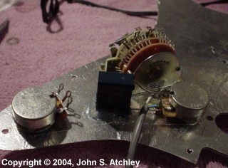
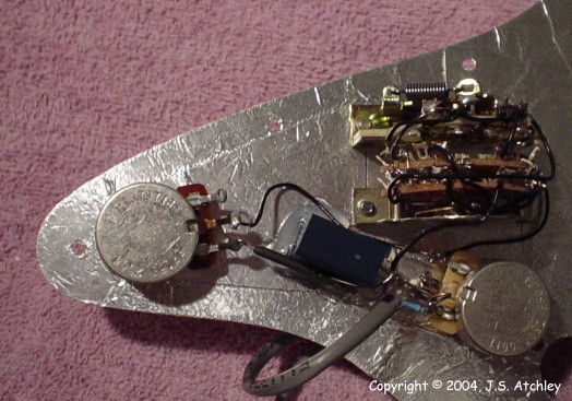
The next picture shows the parts layout as actually implemented in the prototype. This
illustrates the optimum placement of the the two switches, the two pots, and the isolation
capacitor. The latter is glued down over the hole where the neck tone pot formerly
resided.
Note that the capacitor here is only a 275VDC unit as it is getting very difficult to find
400V film capacitors in suitable values (suitable values are from 0.22uf to 0.47uf).
This particular capacitor is availalble from Mouser electronics as stock number 539-158X334.
The switch shown is a "super switch" from Stewart MacDonald's, it is very similar if not identical
to the EP078 from Allparts. DiMarzio sells a similar switch with slightly different
mechanical construction. The terminals on the plastic enclosed Yamaha switch are in
different positions – if you decide to use it you will need to revise the drawing suitably.
When examining the following detail pictures please note that I am not
especially proud of the workmanship. While all of the connections are electrically
sound I did not realize how unattractive some of the work was until I looked at the full-size
high-resolution images on the computer. A couple of years ago I had bypass surgery
and while it did wonders for my health I noticed shortly thereafter that my near vision seemed
to have degraded very noticeably. I recently got new bifocals with the strongest "add"
the optometrist was willing to give me and I still can't see all that well for fine detail work.
I guess I am going to have to get a big lighted magnifier because, while this work
is serviceable enough that I would never criticize it if done by an amateur, it doesn't meet
what I expect from myself.
The following two pictures show closeup detail of how the volume pot and isolation capacitor
are wired. The isolation capacitor is glued to the pickguard with hot-melt glue.
With both ends of the top lead secured (one at the firmly glued capacitor and the other at the
volume pot) the lead makes a fine bus for attaching nearby ground wires.
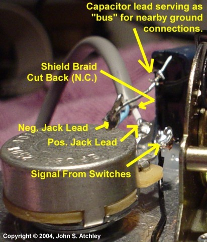
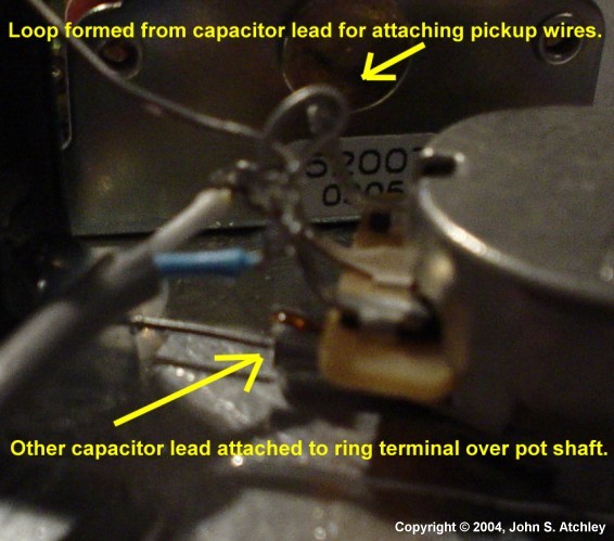
Note that since the capacitor lead made such a nice "bus" the loop for attaching the pickup
leads wasn't really necessary. Since it seems we like to change our pickups more often
than anything else I usually leave a loop so they can be easily desoldered and resoldered without
messing up the pots. In this case the "bus" would have served as well. Note also
that the braid on the shielded jack cable is cut back and not attached at this end. At the
jack end the braid and ground are connected to the same terminal of the jack.
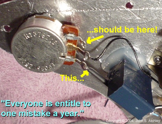
When I moved the tone pot and rotated it from the wiring diagram I drew, I failed to make the
huge mental leap that since the pot had been rotated about 180 degress the bottom terminal
would now be the top terminal... So, don't make the same mistake or your tone pot will work
backwards, too! 
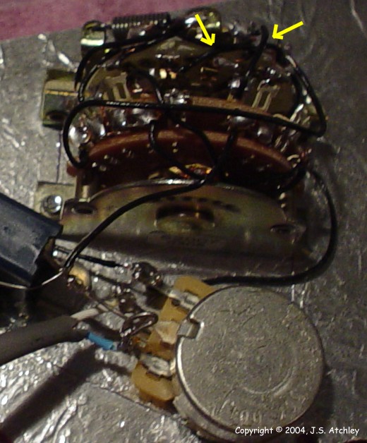
The next picture shows the back of the pickguard all wired up and waiting for pickups.
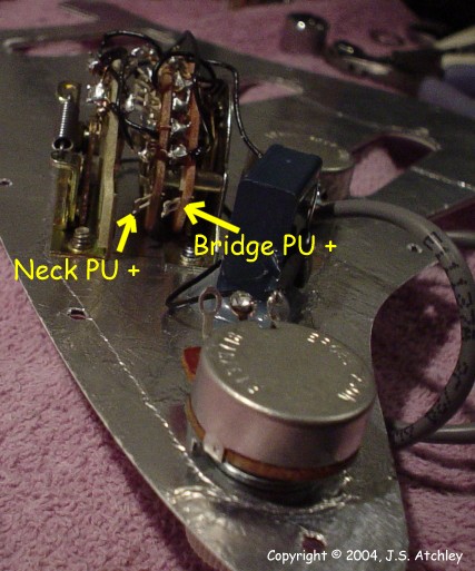
If you look very closely at the next detail shot you may notice that there seem to be "extra"
wires on the stock Fender switch that don't appear on the wiring diagram. Since only one
half of the switch is used, I have tied each terminal pair from the two poles together to
enhance reliability.
The next two pictures show where the pickup leads should go.
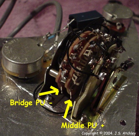
| 
