Mike Richardson's Strat™ Wiring
This modification does not alter the appearance of your guitar.
Updated 9 April, 2004
This design was sent to me by Mike Richardson. The original drawing used a DiMarzio switch which had the
terminals in strange positions when compared to the double-wafer switches from Allparts, WD, etc. This
caused some confusion so Mike was kind enough to draw up this new schematic using the more common switch.
Thanks Mike!
I haven't built this, but it looks interesting and several people have raved about it in the forums.
You can get the five-position, 4-pole switch from WD.
Allparts sells a very similar switch as part number EP078. You could
also use the plastic Yamaha switch (not recommended) or the DiMarzio switch but keep in mind that the terminals
will be in different positions with those switches and you will have to figure out where the wires should
really go yourself – if you're not up to that I highly recommend that you stick to the Allparts switch!
This is a fairly complex diagram, so take your time and pay very careful attention. Double and triple check
everything! Please don't e-mail me with questions because I haven't built this so this diagram
and Mike's notes (presented below) are all the information I have on this modification! Mike is a member
of the forums so you should be able to contact him there if need be.
Here are Mike's own words on the modification:
1) I never use the middle pickup alone, so that sound was replaced
by "bridge + neck."
2) This wiring works best with cleaner, brighter sounding pickups.
Most rail-type units will be too muddy. Joe Barden's should be
fine. I have used this setup with Duncan SSL-1s, APS-1s, Vintage
Rails, and Fender Lace sensors (Silver and 2 Gold) with fine
results.
3) I use a phase switch (not shown) on the neck pickup for more options.
4) Make sure the tone pots are wired as shown, this gives even more
tonal options.
5) If using Lace Sensors, be sure to use the newer ones with the
third (green) wire.
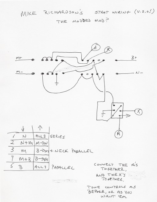
Here are the sounds available, in case you can't read the list
on the diagram itself: With the pull pot down, you get, 1) bridge,
2) bridge + middle, 3) bridge +neck, 4) middle +neck, 5) neck. With
the pull pot up, the tones are 1) all 3 pickups in parallel,
2) bridge +middle in series, 3) bridge +neck in series,
4) middle +neck in series, 5) all 3 in series. Again, the tone
controls have a lot of effect on the sounds, particularly the series
combinations. I leave the choice of tone capacitors up to the
individual, but I tend to use .02 mfd or thereabouts. By all means,
experiment, and have fun with it!
Mike Richardson
|
Here is a slight variation on the above, submitted by Mike after some discussion of it in the forums.
Here is a lefty version of Mike's Strat scheme.
Here is another schematic from Mike Richardson. This one uses a standard Fender Strat switch and a DPDT
push/pull pot to achieve some interesting combinations. Again, I haven't built this but there has been
quite a bit of discussion of it in the forums so you might do a search there.
Here is Mike's schematic of an 80's "The Strat" - he uses parts available from Mouser instead of the
special Fender switch.
Here's a diagram for the early 80's Fender "THE Strat", sometimes called a
"Super Strat" back then. The diagram also works for the similar Walnut
Super Strat. My pic uses an easy to find Mouser switch, and not the goofy
custom job Fender used. In the first "mode", the sounds are the normal 5
you'd get with any stock Strat. In the other mode, starting at the bridge
position, you get: B+N B+N again, which is kind of a drag... M^N M^(B+N)
M^B

+=parallel, ^=series

Mike Richardson
|
|
