How to Read Simple Schematics
Throughout these pages you'll find a number of electrical schematics. I use these instead of "pictorial" wiring diagrams for three reasons:
-
For those with any background in electronics, they are much easier to interpret. They facilitate understanding how the circuit works which in turn facilitates modification of the "canned" circuit.
-
The physical makeup of components -- especially switches -- can vary widely. A "picture" drawn using a cheap Squier pickup select switch will differ greatly from one drawn using a more robust switch from a "real" Fender, for example. The shape of the switches are different and the location of the solder terminals radically different even though the switches are electrically equivalent.
-
Electrical schematics are much easier to draw!
Learning to interpret these few simple symbols can open a whole new world of understanding re. guitar and FX circuits.
Fixed Resistors:
A resistor impedes the flow of current in a circuit. Unlike capacitors and inductors, the amount of impedance or resistance is independent of frequency. Thus, resistors and their cousins potentiometers are combined with capacitors in tone shaping circuits. This is an oversimplification but adequate to understanding the schematics on these pages. Resistance is measured in ohms.
You will often hear the terms "k," "kohms," or "killiohms" which all refer to "thousands of ohms" -- a 470k resistor is 470,000 ohms. You won't often encounter a fixed resistor in a guitar, but they are quite common in amplifiers.
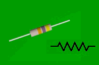 |
| Fixed Resistor |
|---|
Most fixed resistors look similar to the above, a simple cylinder with colored stripes to indicate the value. The above is a carbon resistor. Metal film resistors are generally better -- they are usually of tighter tolerance and not given to changing value as much with age. Metal film resistors look similar to carbon ones but generally have a shinier surface and a "melted" appearance with slight bumps at the ends. There are also wire-wound resistors but they should be avoided unless explicitly called for as they are inductive and will alter the tonal response of a circuit.
Resistors are also rated for their tolerance (accuracy) and for their power dissipation capability (rated in watts). It is acceptable to use a resistor with a tighter tolerance (5% in place of 10%) but not the other way around. It is acceptable to use a resistor rated for higher power (1/2W in place of 1/4W) but not the other way around.
Potentiometers:
A potentiometer ("pot") is simply a resistor with a third terminal which connects to a "wiper" which slides along the resistor, changing the resistance between the wiper terminal and the terminals at each end. Potentiometers are measured in ohms, as are fixed resistors. Most American made Strats use 250k pots for volume and tone (those with TBX use a ganged 5k and 1meg pot). Most American made Les Paul style guitars use 500k pots.
There are two main types of potentiometers, linear taper and audio (or log) taper. The latter are the kind used most often in guitars. Audio taper (or just "audio") pots are constructed so that the amount of resistance change per degree of shaft rotation varies from one end of the pot to the other. It's essential to use an audio taper pot for the volume control. The tone control could easily use a linear taper pot but the manufacturers have pretty much stuck to using the same part number as the volume control -- doubtless to reduce manufacturing inventories.
Often, one end terminal is "disregarded" by either not having anything attached or by being shorted directly to the wiper arm -- in these cases the pot is being used as a simple variable resistor (tone controls). In other cases, a signal is applied across the two "ends" of the pot and the wiper arm is connected to the next "stage" of a circuit -- thus, when the pot is turned, the amplitude of the signal "picked up" from the resistor is varied (volume controls).
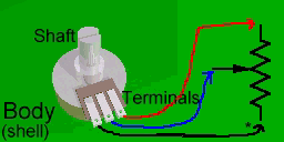 |
| Common Potentiometer and Schematic Symbol |
|---|
| Note that the asterisk (*) in the schematic marks the "low" end of an audio-taper pot. |
The colored arrows in the picture above show which terminal is physically connected to each part of a pot as shown in a schematic diagram. With audio pots, it is critical that you connect the wires to the correct outer terminals -- otherwise your control will be extremely sensitive -- perhaps unusable. Most audio pots you'll probably encounter should have the terminals in the order shown in the picture -- but that isn't guaranteed. When in doubt, the following method never fails: Rotate the shaft of the pot to center. Using a multimeter set to "ohms" (not to continuity test or "diode check") measure the resistance from the wiper (center) terminal to each of the outer terminals. There will be a much lower resistance on the "low" terminal of the pot. (NOTE, if the resistances to each of the outer terminals are approximately equal you have a linear, not audio, pot.)
Generally, the low end terminal and wiper are used in tone controls. For volume controls, the low end of the pot is attached to "negative" or "ground" and the high end of the pot is attached to the positive signal source and the wiper is attached to the positive side of the output jack.
Potentiometers are also rated for the power they can dissipate. However, the circuits in the guitar itself are of very low power and the rating is not important. A few amplifier circuits, though, require special pots.
As with switches, it is important that you use only high-quality pots. If you have occasion to disassemble an inexpensive guitar, I recommend that you replace the pots with higher quality ones simply to avoid trouble later. A guitar, especially one used on stage, is not a very friendly environment. Cheap pots tend to wear out quickly and/or get dirt inside them which will make your controls scratchy. Cheap pots also frequently don't travel all the way to each electrical end. It is not uncommon to find a brand-new inexpensive audio pot which exhibits a significant resistance between the wiper terminal and high terminal even with the pot turned all the way up.
Capacitors:
The impedance (or total resistance) of a capacitor varies with frequency -- this is what makes them useful in tone circuits. At high frequencies the impedance is fairly low, while at lower frequencies the resistance approaches infinity. Capacitance is measured in farads but a farad is a huge capacitance. More commonly you will see measurements of microfarads (uf) which means "millionths of a farad." The higher the value of a capacitor the lower its impedance will be at a given frequency. Capacitors come in a huge range of values and are used for many things -- including to "filter" AC hum out of a power supply and so on. The capacitors used in guitars will generally be in the range of .001uf (for a "bypass" capacitor on a volume control) to 1uf (for an "isolation" capacitor to separate the signal return from a shield ground). Capacitors used for guitar tone controls run from about .01uf to .047uf. One must consider the value of the tone pot when selecting a capacitor to go with it. The higher the resistance of a tone pot, the higher the value of the capacitor must be to achieve the same tonal response. Capacitors also carry a voltage rating but in guitar circuits the voltage rating is only significant for the isolation capacitor because the normal operating voltages in a guitar are miniscule. Of course, in amplifiers the voltage rating is very important.
There are many different types of capacitors ranging from ceramic disk capacitors which are cheap but electrically noisy, to metal film capacitors which are more expensive but "leak" less DC current and are therefore quieter, to electrolytics which are available in very large values -- but which are very noisy and tend to become worse with age. Most electrolytics are also polarized, which means they'll go bad (perhaps disastrously) if installed wrong. For the circuits on these pages, I recommend metal-film capacitors only.
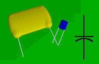 |
| Film Capacitors |
|---|
Size can be a clue to value and voltage rating.
The large one might be around 1uf/400V
the small one around 0.047uf/16V |
Like resistors, capacitors also have a "tolerance" rating. Many of the capacitors used in guitar tone controls are of poor quality with a tolerance of twenty percent. Most "experts" blame wood quality as the reason why two different guitars of exactly the same model may sound distinctly different. There is some truth to this and much of the difference in sound between different models can be attributed to different tonewoods. However, there is a much simpler reason that there is such a wide variety in the tonal response of guitars of similar construction -- different capacitance values in the tone controls. Consider, at twenty percent tolerance, one guitar may have a tone capacitor of .024uf while another has a capacitor of .016uf (using ".02uf" capacitors). That's a total variation of 40% and makes a significant difference in the tone. Add cheap pots (which may not travel all the way to each end and which may have as much as 20% variation in resistance) to the equation and it is quite easy to see how two "identical" guitars can have radically different tone circuits. Note that this applies even to high-end guitars. While top-of-the-line models tend to use better quality pots, they still most often have cheap 20% tolerance ceramic capacitors.
It can be quite difficult to determine what value of capacitor is in an existing circuit because there are several ways they might be marked. Sometimes, they aren't marked at all. This table may be of some help:
Common Pot/Cap Combinations in Guitar Tone Controls:
| Value of Tone Pot | Capacitor Marking | Probable Capacitor Value |
|---|
| 250k | 103
.01
10k | 0.01uf |
250k
500k | 223
203
.022
.02
22k
20k | 0.022uf
0.02uf |
250k
500k | 333
.033
33k | 0.033uf |
| 500k | 473
.047
47k | 0.047uf |
The above values are not set in stone, by any means. In particular don't be mislead by the fact that larger capacitors are often used with 500k pots. This is not because a larger capacitor is needed with the larger pot, but because a larger capacitor can be used without sacrificing the available high frequencies. I.e. with a 500k pot you can use a larger capacitor which means you can cut more treble at the low end without sacrificing treble at the high end.
Switches:
While there are many other types of electronic components, and schematic symbols to go with them, the last component we need to look at for the simple schematics on these pages is the switch. I've saved this for last because there are many different types of switches, and several different ways of showing them on schematics. Regardless of how a switch is physically constructed (slide, toggle, rocker, rotary, etc.) it can be electrically examined as having a certain number of poles and a certain number of positions or "throws." A "double-pole, double throw" (DPDT) slide switch is electrically exactly the same as a DPDT toggle switch, for example.
Each "pole" is a completely separate circuit. One can use a DPDT switch, for example, to simultaneously switch two completely unrelated signals. Each "throw" is a selectable position where the common terminal of a pole is connected to one of the other terminals of that pole. "Off" positions (where no contact is made with any terminal) are generally not regarded as "throws." So, a DPDT toggle switch can be "on-none-on" (no center detent), "on-off-on" (center detent for off position), and in some rare instances even "on-on-on" (and there are different configurations of on-on-on switches, as well). If ordering switches through the mail, it is important that you understand the shorthand used in catalogs -- "on-off-on" indicates a switch which "sticks" at each detent while "(on)-off-(on)" indicates a switch which is spring loaded to the center off position. The "on" positions are called momentary, in the latter case, and you will sometimes see something like "mom-off-mom."
A few simple rules... When multi-pole switches are depicted schematically each pole should be drawn with the switch in the same position. In these pages, you will also find that I always draw a switch that has an "off" position (DPDT on-off-on) in that off position -- that makes it clear that a switch with a center detent is required. Where a switch with no center detent is required, I will draw the switch with the "wipers" set to one position or another. Wherever possible, I draw all the poles of a switch together where they can be attached by a dotted line as in the examples on the left, below. Sometimes that isn't practical -- in those cases I label the switch sections "SW1A," "SW1B," etc. as in the examples on the right, below.
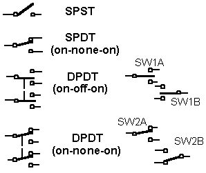 |
| Slide, Toggle, and Rocker Switches |
|---|
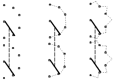
Rotary switches and circuits using them can be quite complex. Rotary switches can have an almost unlimited number of poles and as many as a dozen "throws" or positions. Furthermore, the switch might be of "shorting" or "non-shorting" type. Shorting switches will connect two of the terminals together as the switch is rotated (ie. the circuit from common to position two is "made" before the circuit from common to position one is "broken"). There may or may not be a detent in these "shorted" positions. A Stratocaster pickup select switch is a perfect example of a shorting switch with detents -- there are only three electrical positions or terminals (neck, middle, and bridge) but there are five mechanical positions. At "2" and "4" the common terminal of the switch is shorted to two electrical positions (neck-middle, middle-bridge). In an effort to clarify things a bit, I draw rotary switches as shown below:
 |
| Rotary Switches (two pole, six position) |
|---|
The left is a non-shorting type.
The center is shorting.
The right is shorting with detents in the shorting positions
(and would probably be sold as a two pole, twelve position, shorting). |
For information on selecting the best type of switch for your needs, go here.
|