How Volume and Tone Controls Work
I've combined the discussion of tone and volume controls because, as they are used in Strat circuits, they are so tightly coupled that it is important to understand one to understand the other.
Volume Circuits:
Whenever a current flows through a resistor a voltage potential is developed across that resistor. Further, the voltage is proportional to the amount of resistance and the amount of current. There is a handy little rule, called Ohm's law which states that the voltage across the resistor is equal to the resistance times the current flowing through it:
E = IR
Where: E = voltage (in volts)
I = current (in amps)
R = resistance (in ohms)
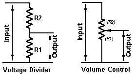
In a series circuit exactly the same amount of current flows through all of the components in the circuit. Since that is the case, and since we know that voltage across a component is proportionate to the current flowing through it and its resistance, we can skip a lot of the interim math and consider two or more resistors in series a simple voltage divider. That is exactly what we do in a volume control, except that we use a single resistor with a sliding tap, called a potentiometer. Consider the schematic below:
 |
| Voltage Divider and Volume Control |
|---|
Let's do a little simple math to see how this works (assume a signal input of 1 volt):
- When the pot is turned almost all the way down R1 might be 1k and R2 249k. The output voltage then would be Vin(1k / (1k + 249k)) or Vin(1/250) or 0.004 volts (4mV).
- When the pot is turned almost all the way up R1 might be 249k and R2 1k. The output voltage then would be Vin(249k / (249k + 1k)) or Vin(249/250) or 0.996 volts.
Since the pot wiper can be smoothly varied from one end to the other we can select 0 percent of the input, 100 percent of the input, or anything in between. Note, though, that at the physical center of the pot we would not be taking 50% of the input signal. Because of the way the human ear responds to sound pressure (amplitude) we have to approximately double the signal strength to make a barely audible difference. For this reason, audio volume controls use "log" or "audio" taper pots. If you built a volume control with a linear taper potentiometer it would be so sensitive that it would be unusable.
Tone Control Circuits:
First, understand that all "passive" controls, such as those used in Strats, are "cut" circuits. You are not "boosting" mid-range when you turn a tone control down -- you are "cutting" or throwing away high frequencies!
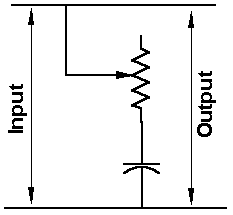
Capacitors have a very useful property, the impedance (total resistance) of a capacitor varies with frequency. At high frequencies the impedance is low, while at low frequencies the impedance is quite high. We combine capacitors and variable resistors (potentiometers) to make adjustable tone controls. There are several ways such controls could be wired, but we will look only at circuits as they appear in Stratocasters. Below is a simplified schematic showing a single tone control:
 |
| Simple Tone Control |
|---|
Remember that the impedance of a capacitor varies with frequency? And that the impedance (resistance) of a resistor does not? In a nutshell, that is why the tone control works. As the variable resistor is cranked up to a very high value, the difference in the capacitive impedance for high and low frequencies becomes insignificant in comparison. Without getting heavily into the math let's use some easy numbers to see how it works. Let's say just for the sake of argument that the impedance of the capacitor is 25k ohms at 4khz, 12.5k at 8khz, and 50k at 2khz and that the pot is a 250k ohm pot:
- When the pot is turned down there is 0k resistance (a short circuit) across it. Therefore, the impedance of the entire circuit will be 50k at 2khz and only 12.5k at 8khz. Thus, high frequencies have a much "shorter" or "easier" path to ground than low frequencies do.
- When the pot is turned up there is 250k resistance across it. Therefore, the impedance of the entire circuit will be 300k at 2khz and 262.5k at 8khz. The impedance is still lower for a high frequency signal -- but only by a very small ratio.
Note that this circuit would not work in a "perfect" world! If the input signal were regulated such that the voltage never varied regardless of the load impedance and the amplifier on the output had infinite impedance and no padding -- this circuit would not vary the tone. However, magnetic pickups are not regulated and they are capable of delivering only a tiny amount of current. I'm trying to avoid complex math in these pages so I'll oversimplify a bit and simply say that as the load impedance (represented by the tone control) goes down, the voltage that is output by the pickup goes down too. Since the first gain stage of the amplifier is basically a voltage amplifier the final signal decreases with the voltage at the tone circuit.
In short, the tone control works because the impedance of the tone control is lower for high frequencies then it is for low frequencies -- which "pulls down" the high frequency output of the pickup. Finally, note that the figures I used in the example above are "blue sky" figures intentionally chosen to emphasize the significance of the varying resistance of the pot. In the real world, a tone control with that significant a difference between the resistance of the pot and the impedance of the capacitor would function more as a volume control than as a tone control!
|