 | S-Tastic™
Three-Pickup
Wiring |
This modification will not alter the appearance of your guitar.
The T-Riffic™ modification for two-pickup guitars was so successful I decided to work up a version for guitars with three pickups. I prototyped this modification on a Route 101 Solimar™ guitar which is similar to a Strat™ guitar. Interestingly, the neck and bridge out-of-phase sound is very different on a Strat than it is on a Tele. While on the Tele this combination is very trebley and twangy it is more difficult to describe on the Strat. This is the second modification I've devised that features this combination (the first was the Strat Lover's Strat). This prototype was the first time I've used this combination on a Strat with vintage-type single coils. On Strat Lover's Strats that I have built I have always used either stacked humbuckers or very hot single coils. I wish I'd tried this with "vintage" single-coil pickups long ago as the results are the best yet.
I really can't decide whether to call this series out-of-phase position twang or quack, but whatever it is there is a lot of it with the right pickups. From the open low string all the way up through the second octave on the high E string this position is in-your-face with tone. The low strings have that sproingy, boomy sound often encountered in country leads and the high strings have an almost chime-like quality.
I also first prototyped the T-Riffic modification on a semi-hollowbody guitar equipped with hot "Texas" humbuckers. The performance there was good, with a sort of hollow-sounding out of phase position, but not as stunning as either the Tele or this Strat-type guitar. Because of the obvious differences in the end result with identical pickup combinations on different guitars I have to conclude that the neck/bridge out-of-phase position is very sensitive to the type of pickups and the guitar design (i.e. the pickup positions along the strings and so on). Note that the modification has been useful and worthwhile on every guitar that I've built – but it has not been as predictable as other things I've tried).
| S-Tastic™ Pickup Selection |
|---|
| Note that the pickup selector switch controls only the neck and bridge pickups – there is one volume control for those two pickups and another volume control for the middle pickup. The middle pickup can be "mixed" with the others at any ratio. |
| Position | Pickups | Tone*6 |
|---|
| 1 |
Neck |
Rhythm |
| 2 |
Neck+Bridge in Parallel |
Rhythm |
| 3 |
Neck+Bridge in Series |
Rhythm |
| 4 |
Neck+Bridge in Series and Out of Phase |
Lead |
| 5 |
Bridge |
Lead |
1 – Positions 1 and 5 are the stock Strat™ positions (when the volume control for the middle pickup is turned all the way down).
2 – The regular Strat 2 and 4 positions are available by selecting positions 1 and 5 and turning the middle pickup volume control all the way up.
3 – The regular Strat 3 position (middle only) is available by turning the middle pickup volume all the way up and the other volume control all the way down (there is no tone control for the middle pickup, though, unless the optional concentric pot is used).
4 – Position 2 is similar to the Tele™ middle position. Position 3 is similar but louder and with more midrange.
5 – Position 4 may sound either hollow or incredibly twangy depending on the type of pickups and their position along the strings.
6 – The rhythm and lead tones are controlled by the same knob but there will be more treble (i.e. less cut) in the lead positions because of the second capacitor in series in the tone circuit. |
The main pickup switching of this modification is identical to that of the T-Riffic modification except that I moved the "series and out of phase" combination from position two to position four. I did this because, with single coil pickups as found on most Strats, this position sounds more similar to the bridge pickup than to a more mellow "rhythm" sound.
The sound of the various positions (especially the out of phase position) will vary depending on the pickups used and their location along the strings. On a semi-hollowbody guitar with hot humbuckers this position was kind of hollow and boomy – an interesting position but not something you'd want to use too much. On a Tele with stock single-coil pickups this position turned out to be an incredibly "edgy" twang. On the Solimar I don't even know how to describe this position but I may just glue the switch there and never play anything else.
The pickup selector switch used is available from Allparts as part number EP078 for around fifteen bucks. Very similar switches with slightly different physical details are available from DiMarzio and WD. On the T-Riffic I used the Yamaha switch. I wouldn't recommend the Yamaha switch as it is kind of delicate. However, that switch is a tad smaller so you might want to use it if you have a very tight or shallow body cavity. If you do need to use the Yamaha switch you can subsitute the switch part of the wiring from the diagram for the T-Riffic mod although this will put the out-of-phase position at two instead of four. Please note that if you do use the Yamaha switch the terminals are in a completely different order.
I highly recommend the optional second tone control. Without the second tone control the behaviour of the middle volume control will be just a touch quirky. With both volume controls turned all the way up and the neck or bridge pickup selected the behaviour will be exactly as on a stock Strat. However, if you roll either volume control off just a little the middle pickup gets isolated from the tone control and the treble will increase. Then, as the middle volume is rolled off further the treble will again decrease as the pickup is mixed out. This isn't a big problem, and might even be used to advantage, as long as you're aware of it.
The only reason not to use the second tone control is if you are adamant about sticking with stock plastic knobs, as I was on this prototype guitar. A friend is having me build him one of these and we will be putting two concentric pots on it. What we are planning for his guitar is to order a Strat pickguard custom cut with only two holes for pots (Warmoth or WD sells these). Each hole will get a concentric pot so that the volume and tone for the main pickups is on one shaft and the volume and tone for the middle pickup is on the other. I plan to add pictures of that guitar when it is done.
If you look closely at the diagram below you will see that the switch terminals are labeled – with "C" denoting the unswitched or "common" terminal, "1" being the active terminal when the lever is in the "neck" position, and so on. If you use a switch other than the Allparts switch shown you'll have to check its terminal configuration against that for this switch and modify the diagram as needed.
The wiring diagram is a "rear view" of the parts – i.e. as if you were looking at the underside of the pickguard.
This is a fairly complex modification and you shouldn't attempt it unless you are handy with a soldering iron and are capable of following the diagram below.
Use 500k pots to provide good isolation between the two volume controls. Note that the single tone control is not a master tone control. A single master tone control doesn't work well with two volume controls in this configuration. Instead, we put the tone control on the "main" pickups – the switched combinations of neck and bridge. This works okay (with a couple of quirks mentioned above).
All capacitors are film type. Do not use electrolytic or ceramic disk capacitors. Values for the tone capacitors (0.01uf & 0.033cap) are suggested starting points. The 0.033uf cap is for the "rhythm" positions on the switch and the 0.01uf cap is placed in series with it to reduce the amount of cut for the "lead" positions. I actually used an 0.047uf cap in place of the 0.033 – this was a tad more than necessary, hence the 0.033uf recommendation. It's okay to use the 0.047 cap if you wish, as the 500k pot effectively eliminates it from the circuit at full treble anyway.
You should shield the guitar as described in the Quieting the Beast shielding instructions. If you do so, then the various points in the circuit flagged "SG" (for signal ground) should be tied to the non-grounded end of the isolation capacitor. The other end of the isolation capacitor is attached to the shield ground (the "rake" symbol above) as described in the Quieting the Beast modification. If you choose not to use the isolation capacitor (the .22uf capacitor above) then it is best to tie all of the points flagged "SG" to a single point (such as the shell of the volume pot). This is called "star grounding" and reduces susceptibility to noise. Do not add jumpers between pot shells – those are ground loops which are naughty.
Note that I'm recommending a .22uf 200V isolation capacitor instead of the .33uf 450V capacitor described in Quieting the Beast. The pickup select switch used here eats up a lot of room and it would not be possible to fit the larger capacitor into the pickup cavity of some Strats. The smaller value capacitor may raise your noise level some. If this is objectionable you can omit the capacitor entirely (effectively replacing it with a straight piece of wire or simply soldering all of the "SG" wires to the shell of the volume pot).
Also note (from the accompanying photos) that I used this modification to test a slightly different approach to the problem of isolating the strings. Instead of using a very large capacitor between signal ground and all of the shielding, I used a fairly small (0.1uf) cap between the cavity shielding and the string ground. The smaller capacitor provides a little more protection from AC shock (see the article on shock hazards). The smaller capacitor is also physically smaller, making it easier to position in a tight body cavity, and more readily available. This approach does have a drawback, though – if metal knobs are used they may not be isolated. As far as noise rejection is concerned, this scheme worked at least as well as isolating the entire shield through an 0.33uf capacitor.
Note that in both of the series positions (switch positions three and four) the neck pickup's negative lead is lifted above ground. This can cause two problems:
- If there is a connection between the pickup ground lead and the shield ground then position will be completely dead and position four will be only the neck pickup.
- There may be an increase in noise in the series positions. There will almost certainly be a loud buzz when you touch the neck pickup cover (on pickups with "grounded" metal covers) in these positions.
Neither of these problems is likely to occur with typical Strat pickups. If you do encounter one of the above problems please refer to the T-Riffic modification for tips on solving the problem.
Pictures...
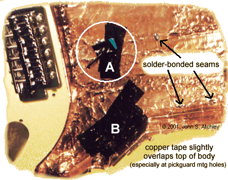 |
- A – Note the alternate method (from that described in the Quieting the Beast modification) of isolating the strings. One lead of the capacitor is soldered to the bridge ground wire and the other is soldered to the copper shielding in the body cavity. The insulating tape prevents the non-grounded lead from shorting to the shielding or to the pickups. This small mylar capacitor (0.1uf 200V) provides some protection from AC shock and good noise performance. Note that an 0.1uf 450V cap would be better. Also note that only the bridge and strings are isolated – if metal knobs are used on the pots they will not be grounded, neither will the selector switch lever.
- B – The switch used is quite large. On this prototype guitar I had to bend the contacts slightly to make it fit. The black electrical tape keeps those contacts from shorting against the shielding tape in the body cavity.
- The shielding tape overlaps onto the top of the body slightly all the way around the cavity. I usually make it a point to carry the tape all the way out to at least two or three of the pickguard mounting holes. The shield ground is carried from the foil on the back of the pickguard to the shielding tape in the body cavity, and then on to the bridge, by the contact between the pickguard and body. This eliminates having a pesky bridge ground or body ground wire to desolder every time you need to work under the pickguard.
- Unless you know that the copper tape you are using has conductive adhesive make sure you electrically bond all of the pieces of shielding together with solder. Even if the tape has conductive adhesive this is a good idea because tapes with conductive adhesive usually specify that a 50% overlap is required for good electrical contact. There are cheaper tapes than copper shielding tape, such as aluminum plumber's tape and the like. They work but you can't solder to them.
- Shielding the tiny cavity around the jack is unnecessary.
- Note the wrinkles in the shielding tape. This body was very rough inside. The tape is actually pressed quite tightly to the body all over. The rough body cavity isn't a problem, but I wanted you to know that the tape goes on very easily and smoothly and also that it should be pressed tightly against the body all over.
|
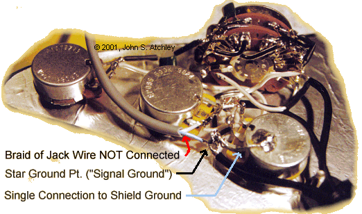 |
- Note that all signal ground wires attach at a single point, and that there is only one connection between that point and the shield. You could also solder all of the wires to the shell of the volume pot and bend the ground terminal of that pot back against the shell but some folks have trouble soldering to pot shells – that's why I designed the original shielding instructions (see "Quieting the Beast") such that soldering to pot shells was unnecessary.
- It isn't essential to use a two-conductor plus shield wire for the jack, but if you do then only attach the braid at one end. I usually attach the braid and ground conductor together at the jack end, and trim the braid back at the control end.
- You can get a basic feel for how I layed the wiring out from this picture but you really need to work from the wiring diagram above for the details. It's very nearly impossible to decipher close wiring like this from photographs.
- The oblique lighting (a crummy desk lamp perched on some books) in this photo emphasises the small wrinkles in the aluminum foil on the pickguard. The foil is actually quite smooth and needs to be to make sure that the pickguard lays flat on the body when it is reinstalled.
|
|
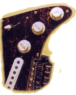
- As the finishing touch, replace that middle knob with another "volume" knob.
|
| 