 | T-Riffic™
Two-Pickup
Wiring
Modification |
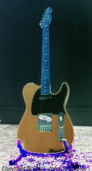
This modification will not alter the appearance of your guitar.
Last updated: 10-20-2002
| T-Riffic™ Pickup Selection |
|---|
| Position | Pickups*1 | Tone*2 |
|---|
| 1 |
Neck |
Rhythm |
| 2 |
Neck+Bridge in Series and Out of Phase |
None*3 |
| 3 |
Neck+Bridge in Parallel |
Rhythm |
| 4 |
Neck+Bridge in Series |
Lead |
| 5 |
Bridge |
Lead |
1 – Positions 1, 3, and 5 are the stock "Tele™" positions. Position 4 is similar to 3 but louder and with more midrange. Position 2 may sound either hollow or reedy depending on the type of pickups and their position along the strings.
2 – When the single tone control option is chosen the "rhythm" and "lead" tones are controlled by the same knob but there will be more treble (i.e. less cut) in the "lead" positions because of the second capacitor in series in the tone circuit.
3 – You can optionally jumper the only unused terminal on the Megaswitch (posistion two of pole four) to either tone capacitor to provide tone control for this position. |
I designed this circuit for Tele™ style guitars but it works equally well with any guitar having two magnetic pickups. I have now designed a similar modification for guitars with three pickups. See the S-Tastic™ modification.
This site is really about getting people to experiment and try new things. Sure, I've come up with some neat mods, but I've only just scratched the surface and I love it when the light comes on and people take what I've done to another level. Here's an e-mail I received from Hal, who combined the T-Riffic modification with a switch to select between series and parallel wiring of a humbucking pickup. Well, here, I'll let Hal tell it in his own words.
While I'm at it here's a testimonial that just came in from across the pond. I've received a lot of positive feedback on this modification, but I chose to print this one because Will points out something that can't be mentioned too often – the tiny, crowded terminals on the Yamaha switch require a steady hand.
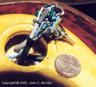
I first prototyped the T-Riffic circuit on a Robin Savoy semi hollow body (two humbuckers, one volume, and one tone control). That guitar didn't have room for a Strat/Tele style switch (and I wasn't too enthusiastic about cutting a slot in the guitar anyway) so I used a miniature sealed 6-position, 4-pole rotary switch. I wired the sixth position for bridge pickup only with no tone control. I don't have any plans to do another of these soon as wiring the switch was a royal pain in the neck. The switch is about the size of a quarter and has 28 terminals, 26 of which were used (see photo below).
The sound of the two new positions will vary depending on the pickups used and their location along the strings. On both guitars I've modified the series-in-phase position is similar to the standard parallel position but with more volume and midrange. The series-out-of-phase position on the Savoy (hot Rio Grande humbuckers) is interesting but kind of "boomy" and not something you'd want to use all the time. The out-of-phase position on the Tele was the big surprise. Can you say twangggg boys and girls! On the Tele (1996 standard) the series-out-of-phase position is just unbelievable. It almost sounds like a wah effect.
You can elect to build the circuit with either one or two tone control pots. When you only use one tone control pot the "lead" positions still have more treble (less treble cut) because of the second capacitor added in series in the tone control circuit. If you want two tone controls on a guitar that didn't originally have the extra pot, use the concentric pots available from Warmoth.
The pickup selector switch is a Yamaha 5-position, 4-pole switch. Stewart MacDonald sells these as #4650 for about fifteen bucks. For carved-top guitars, #4651 is the same switch with a longer shaft. A reader recently told me about a higher-quality 5-position, 4-pole switch. This is the Oak switch available from Allparts and others. Once I get a chance to prototype this modification using that switch I will add circuit diagrams using that switch. More construction notes follow the schematics below.
Here are the wiring diagrams for the two versions. Note that these are drawn more like physical diagrams than typical schematics. The yellow-highlighted connections should be made after the switch is installed in the control plate. The violet letters correspond to the letters on a later photo of the switch. All other connections to the switch should be made before the switch is installed – "benchwork" is much easier and you don't have to worry about things like scratching or dripping hot solder on the paint.
NOTE: The violet letters in the schematics above correspond to the letters in the photograph of the Yamah switch further down the page.
 10-20-2002 This partial schematic shows the switch wiring when using an Allparts number EP078 double-wafer switch. Other double-wafer switches may have their terminals in slightly different positions relative to the frame, but all I've seen have had the terminals in the same order relative to each other.
All capacitors are film type. Do not use electrolytic or ceramic disk capacitors. Values for the tone capacitors (0.01uf and 0.02uf) are suggested starting points with 250k pots. Replace 0.01uf with 0.02uf and 0.02uf with 0.033uf or 0.047uf if using 500k pots. Build the circuit with the suggested values. Then, if you find you want more treble at the high end, decrease the size of the capacitors. If you find you want the controls to be more effective at the low end (more treble cut), increase the size of the capacitors.
Note that you should shield the guitar as described in the Quieting the Beast's Cousin shielding instructions.
Note the connection to the shell of the volume pot. On most stock guitars this is accomplished by bending the ground lead of the pot back against the shell and soldering it there – the remaining connections shown to the negative lead of the pot are then often soldered to the pot shell.
A – Ground terminal soldered to pot shell.
B – Other connections grounded at pot shell.
The shielding picks up it's ground connection via the pot shell being grounded to the metal control mounting plate.
Note that in both of the series positions (switch positions two and four) the neck pickup's negative lead is lifted above ground. This can cause two problems:
- If there is a connection between the metal pickup cover and the shield ground then position two will be completely dead and position four will be only the neck pickup.
- There may be an increase in noise in the series positions. There will almost certainly be a loud buzz when you touch the neck pickup cover in these positions.
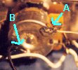
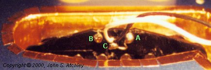
Both of these problems can be solved with a bit of care and planning. The trick is to break the existing connection between the negative lead of the pickup and the pickup cover and replace it with a new connection between the shielding and the metal pickup cover. This will leave the pickup cover grounded when the negative lead of the pickup is lifted above ground in switch positions two and four. Refer to the photos below for one method of doing this (photos are of a shielded 1996 standard MIM Tele).
A – The negative pickup lead connects here.
B – The positive pickup lead connects here.
C – This is a tab on the metal pickup cover.
[1996 standard MIM Tele – others may vary.]
1 – Cut the jumper to the negative pickup lead right at the negative pickup lead.
[Do not cut either of the pickup leads!]
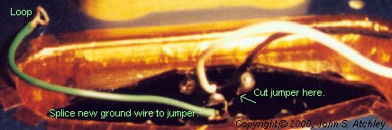
2 – Form the wire jumper that remains attached to the pickup cover into a hook.
3 – Solder a new ground wire to that hook.
4 – The other end of the ground wire has a loop that just fits over the pickup mounting screw.
5 – The loop is tinned with solder.
1 – The loop on the new ground wire goes on the pickup mounting screw, between the
spring (or surgical tubing) and the foil on the back of the pickguard.
Another way to do this would be to use a longer ground wire for the pickup cover and solder it to the copper shielding in the body cavity. That method would probably be more reliable in the long term but has the disadvantage that if someone lifts the pickguard carelessly they are going to rip the shielding out of the guitar.
Here is a view of the Yamaha switch wired up and ready to install. Only the connections to the guitar remain to be made. This is for the single tone control version. Note, this photo is for gee-whiz value only. Not all of the connections show clearly in this photo. You should work from the wiring diagrams above when wiring the switch.
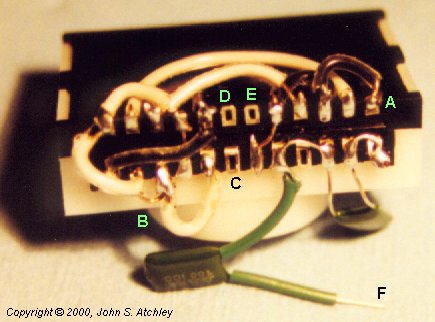
Letters correspond to the violet letters in the first two wiring diagrams.
A – The ground lead will connect here.
B – This loop of bare wire makes a convenient place to attach the hot lead from the volume pot.
C – The positive lead of the neck pickup attaches here.
D – The positive lead of the bridge pickup attaches to this terminal.
E – The negative lead of the neck pickup attaches here.
F – Run a wire from here to the tone pot.
This is a lot of terminals in a small space (this switch is about the same size as a stock switch, remember). As you can imagine, you shouldn't attempt this modification unless your soldering skills are up to it. Finally, note that the jumper wires shown here are pretty thin yet this switch barely fit into the control cavity because the wire loops on the side of the switch were pushing against the wall of the cavity. I had to apply a lot of pressure to get the control plate back into place. Use the finest wire you can find or make smaller loops that come off the end of the switch (there isn't much clearance from there to the bottom of the cavity, either). I think that the next time I do this I will use the inner conductors from telephone wire for the intra-switch jumpers.
The terminals on this switch are very brittle and will break if you bend them very much at all. I've been slinging solder for over twenty years and I broke one of the terminals on the first switch I used. Work slowly and exercise patience and no, I don't sell pre-wired switches. To make it worth my time and frustration I would have to charge more than any sane person is willing to pay!
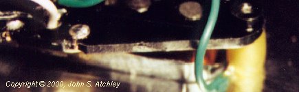
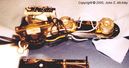
Mount the new switch before cutting any wires to the old switch (see photo below). This way you confirm that the switch fits the mounting plate and that you have the correct screws to mount the switch before you cut the old switch out of the circuit. The Yamaha switch does not come with mounting screws and chances are that the screws from your old switch won't fit! Finally, this holds the assembly steady so you can solder the wires onto the new switch. Use a heavy "shop-towel" paper towel or a rag to keep the assembly from damaging the paint.
In the final photo (below) everything is wired up and we're ready to stuff the switch into the too-tight control cavity. Once that's done nobody will know your Tele isn't factory stock until you throw her into fourth or fifth gear.
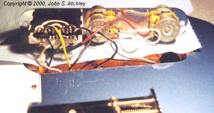
Not all connections are visible here. Work from the diagrams above.
The original knob may not fit the Yamaha switch. Even the Strat-style knob that I ordered from StewMac that was supposed to fit this switch had too large a slot. I used a shot of clear silicon RTV to attach the original Tele "hat" knob.
| 