Quieting the Beast, Shielding a Strat™
This modification does not alter the appearance of your guitar.
Last updated 1-3-2004
What some people have said after shielding their guitars.

Introduction
Most guitars with single-coil pickups suffer to some degree from hum. Almost all are much noisier than they need to be, because the manufacturers don't bother to shield them well and don't follow simple electronic wiring principles that have been known for decades. This holds true even for many premium guitars costing thousands of dollars. Even some guitars equipped with humbuckers can benefit from good shielding and grounding – guitars that pick up local radio stations are good examples.
These instructions apply primarily to guitars with regular magnetic pickups. Doing the shielding won't cause any problems with newer "noiseless" pickups like Lace sensors, but neither will you see much reduction in hum (which should be almost nonexistant anyway). You may, however, notice a significant reduction in buzz from flourescent lights and such. Often, this noise is picked up in the controls rather than the pickups. That is why you will sometimes hear this noise even with humbuckers or with a Strat in the 2 and 4 positions.
Many guitars with single-coil pickups will benefit noticeably from shielding and star-grounding as described here. Generally speaking, the more noisy your guitar is the more noticeable the improvement will be. In fact, I am beginning to hear from more and more people who are opening up new guitars and finding shielding paint, etc. Good wiring and shielding are by no means yet the norm, but before you start ordering shielding supplies have a quick look in your guitar and also compare it to other similar guitars – if your guitar is already significantly quieter than most other similar models, you aren't going to see a lot of improvement after following these instructions.
These step-by-step instructions and illustrations are for Stratocaster™ type guitars but the principles and techniques can be applied to any guitar. Shielding a Telecaster™ type guitar is even easier – here are some photo-illustrated instructions using a 1996 Standard (MIM) Fender Tele™.
Shielding and regrounding your guitar will not signficantly alter its tone, other than that it may sound a bit more alive because faint harmonics that were buried in hum can be heard more clearly when the hum is removed. Also, you will typically be able to play at higher gain levels before hum becomes objectionable. This means more tube saturation and sustaining feedback. These instructions have been online at various URLs since early in 1996. During that time I have never received an e-mail from anyone who wanted to know how to put the hum back into their shielded guitar!
Probably the greatest benefit of reducing hum is the accompanying increase in sustain and dynamic range. As you reduce hum you can crank the gain higher on your amplifier before the hum becomes intrusive. With the increased gain you get better sustain and you can vary your picking attack for much better dynamics as you play.
I think many guitarists have become so accustomed to hum that they've fallen into the habit of adjusting amplifier volume to the point just below where hum becomes annoying. I've heard from a few people who reported that there wasn't much reduction in hum after shielding. Occasionally we find that they missed something in the instructions. Less frequently we find that they had really hot overwound pickups and/or pickups mounted high in the pickguard (i.e. for a guitar with high action) and in these cases directly shielding the pickups solved the problem. Still less frequently we find that they had shielded one of the rare guitars that was pretty well shielded at the factory so there wasn't much noise to begin with (in the last few years more and more guitars are recieving at least a shot of shielding paint by the manufacturers but even this is still far too rare). But, almost all of those few who initially report little reduction in hum say things like, "my guitar sounds much better now and sustains better but it still hums about as much as before." Most have had the good grace to feel a bit sheepish when I point out that it sounds better and sustains better because they are playing at much higher gain levels – and that they can play at those higher gain levels because of the reduction in hum!
Principles and Practices
Good practices and principles improve the noise resistance of any circuitry. These practices are almost universally applied by all electronics manufacturers except those making electric guitars! Manufacturers routinely sell expensive guitars containing wiring that a manufacturer of $25 cassette players would never tolerate.
The practices and principles almost universally ignored by electric guitar makers are simple and have been known and practiced by manufacturers of other electronic items for decades:
- Shield components that are susceptible to noise – especially long wire runs, coils of wire, and high impedance circuit paths.
- Avoid ground loops.
That doesn't sound too difficult, does it? It's not. These instructions will show you how to apply the simple principles above to reduce hum and vastly increase immunity from high-frequency interference as well. Though the before and after schematics look very similar, in reality quite a few ground wires have to be moved to correct the wiring practices that contribute to noise. These non-artist's renderings show the differences between the stock factory wiring and the properly shielded and grounded circuit much more clearly.
Skills Needed
You will have to do some soldering, if you've never soldered I recommend that you get a pamphlet on the subject and practice on scraps of wire and such before working on your axe. You also need the ability to follow written instructions and the patience not to rush through the modification haphazardly. Beyond that, if you've learned to play guitar then you should have the manual dexterity to follow these instructions. I suggest that you print this page, read it through several times, and then check off each step as you complete it. (Note that these instructions assume a Stratocaster guitar -- modify as needed for other types.)
Tools Needed
All of the following are available at Radio Shack stores. Many hardware stores will also carry these tools and possibly at better prices.
- Soldering iron (an inexpensive 30-watt pencil is fine). Note that I've intentionally developed instructions that avoid having to solder any wires to the shells of potentiometers. Many people have difficulty making good connections to pot shells without damaging the pot or other components. If you must ignore my advice and solder directly to a pot shell, you will need a larger iron or a soldering gun.
- Desoldering pump or bulb.
- Wire cutters and strippers.
- Sharp hobby knife or single-edge razor blades.
- Small crescent wrench or hollow-shaft nutdriver that fits the mounting nuts on your control pots.
- Screwdrivers that fit the pickup mounting screws and pickguard and jackplate mounting screws.
- Heat gun (optional). Very nice for shrinking heat-shrink tubing very cleanly for a professional appearance – however, don't go out and buy one unless you plan on doing a lot of wiring.
Materials Needed
- Resin-core electrical solder. Paste flux is also nice to have around for that occasional component lead that just won't take solder.
- Desoldering braid.
- About 1' of "audio" cable which has two insulated conductors inside a single shield.
- A few feet of insulated 20 or 22 guage wire (you can use the inner conductors from the audio cable mentioned above).
- Masking tape and a pen that will write on masking tape.
- Two large uninsulated ring terminals that will fit over the mounting shaft of the pots on your guitar.
- Heavy duty aluminum foil (available at any grocery store). One reader reports he found a suitable copper foil at a craft store (Michael's) for about $8.00. The aluminum foil is used on the back of the pickguard and may be used to shield the body cavity. If you use one of the other options to shield the body cavity, and your pickguard is already completely covered with metal foil on the back, you don't need this.
- Craft spray trim adhesive. I usually use 3M but one reader reports that he got great results using Elmer's Spray Adhesive at about 1/3 the price of 3M. This is used to attach the aluminum foil to the back of the pickguard and may be used to attach aluminum or copper foil in the body cavity.
- Electrical insulating tape (also nice to have some heat-shrink tubing but not critical).
- Either a small bottle of rubber cement or thin conductive copper self-stick tape or non-ferrous conductive paint. You can also use spray trim adhesive on aluminum foil to make a "poor man's aluminum tape." Finally, most hardware stores carry aluminum tape used in sealing duct work. That tape will work but you have to be sure that there is electrical contact between the inidividual pieces of tape. (NOTE! We're talking about the shiny real-aluminum tape here. Do NOT use aluminized cloth "duct tape" -- it is NOT conductive and is useless as a shield). NOTE: Some copper foil tape has a non-conductive adhesive which means you need to tack-solder the pieces together (or fold over the edges and stick them down with tape or thumbtacks) to electrically connect the various pieces. I have found a source of copper tape with conductive adhesive intended specifically for shielding. Allied Electronics (800-433-4700) part number 708-8092 (cat# 956) is copper tape with conductive adhesive -- 1/2" wide by 36 yards (enough for several guitars) -- and quite expensive ($64.59). If you use this kind of tape, you don't need to fold over the edges, but you do need to do a 50% overlap. Which method is "best?"
- For ease of use (easiest to hardest):
- Conductive paint
- Copper tape with conductive adhesive
- Copper tape with non-conductive adhesive
- Aluminum tape with non-conductive adhesive
- Foil and glue
- For most effective shielding (though in most cases you probably won't be able to hear any difference between the first three):
- Copper tape
- Foil and glue
- Several coats of good conductive paint
- A skimpy coat of conductive paint
- For cost effectiveness (least to most expensive):
- Foil and glue (this is what I've used on many of my own guitars)
- Conductive paint or plain copper tape
- Copper tape with conductive adhesive
- If you have hot "overwound" single coil pickups (Texas Specials, for example) you may optionally want to get some copper tape and carefully shield the coils of the pickups themselves following these instructions.

- An 0.33uf, 400V metal film capacitor. Note, this is a change (10/06/1998) from the 1uf capacitor previously recommended. This capacitor was originally placed to prevent DC shocks from defective tube amplifiers. I hadn't given much thought to blocking AC because I always check wiring recepticals and so on. A recent discussion on the REC.MUSIC.MAKERS.GUITAR newsgroup brought it to my attention that many others don't and that some gigging musicians simply can't check/control wiring. This new value will provide some protection from the dreaded PA-and-Amp-on-different-polarities problem while providing much better noise performance than the parallel combination of a tiny capacitor and resistor recommended by some. This will limit current on a 120V, 60hz system to a maximum of about 30ma – certainly enough to get your attention but less likely to be lethal for most people. Even so, if you gig a lot and don't have control over the wiring – play it safe by either deleting the string (bridge) ground connection entirely or by using the tiny capacitor and parallel resistor method to isolate the strings. See the very important article on electrical shock.
These materials are available from any number of suppliers. Also, some suppliers are now making custom
items such as pre-cut shielding foil for pickguards and what have you. Bill Horner, a regular denizen of the forums,
has put together a pdf document listing some sources for these supplies.
Thanks Bill!
One Step at a Time
New – 10-19-2002 I haven't shielded any Strats since I got my digital camera, but a guy name of Frank was kind enough
to take some pictures and send them to me when he shielded his Squier recently. Here are a few of the
best pictures along with my commentary.
Check each step off as you complete it. Remember read through all of these steps several times to fix the "big picture" in your mind before you pick up any tools!
- Remove the plate that holds the input jack. Draw yourself a little sketch of where the wires are attached, double check the picture, and then desolder the wires from the jack.
- Remove the entire pickguard assembly. Cut the small wire that runs through the body to the tremelo (vibrato) approximately in the middle.
- Carefully pull the wires that went to the output jack through the channel in the body. You should now be able to lift the pickguard assembly completely away from the body. There should be nothing tieing the pickguard assembly to the body at all.
- Draw (and double-check) a complete diagram of the wiring of all the components on the
pickguard. New – 10-19-2002 If you
have a digital camera, take a lot of photos of the circuit from every conceivable angle. This is your ticket to restore your guitar to original condition in case of difficulty.
There are minor variations in wiring from model to model so e-mailing me something like "help, where does this
wire go" is probably not an option!
- Some factory pickguards have a skimpy patch of foil on the back under the controls. Other pickguards have foil covering the entire back of the pickguard. If yours does not have foil covering the entire back of the pickguard:
- Remove all the controls and pickups from the pickguard. You don't need to disconnect any wires, just mark the pot shells to indicate where each control was, mark the back of each pickup to indicate its position, remove the knobs from the pots and switches, remove the mounting nuts from the pots and the mounting screws from the switches and pickups, and pull the entire assembly away from the pickguard.
- Lay the pickguard face down on a sheet of newspaper.
- Spray the back of the pickguard with a light coat of 3M spray trim adhesive. Let the adhesive dry until it is tacky.
- Move the pickguard to a fresh sheet of paper. Lay a piece of heavy-duty aluminum foil over the back of the pickguard and, working from the center outward, press it flat to the pickguard -- carefully working out creases and bubbles.
- Using a razor blade or sharp hobby knife trim the excess foil around the pickguard and from within the cutouts. Be careful as it is very easy to damage the pickguard especially around the bevelled edges.
New – 10-19-2002 Note, after doing a few of these I've discovered that the easiest way to trim the foil without
damaging the pickguard and without leaving bits of foil to show from the front is to work from the back of
the pickguard, actually trimming the foil 1/16 to 1/8 of an inch in from the edge. Then, take a rag and
rub the exposed adhesive along the thin bands at the edges, if not removing the adhesive, at least "dirtying"
it enough that it won't stick the pickguard to the guitar body permanently when you reassemble the guitar.
- Reinstall the pickups and control assembly.
- Pull the loose end of the tremelo ground wire (the wire you cut when you removed the pickguard) through the body into the tremelo cavity on the back.
- Clean all of the sawdust, dirt, and polishing compound residue out of the pickup and control body cavities.
- Shield the pickup and control cavities using one of the three methods outlined below. Regardless of the method used, the shielding must carry onto the face of the guitar particularly at the points where the pickguard mounting screws enter the body. Be careful though to apply shielding only where it will be covered and hidden by the pickguard. Use one of these methods:
- Conductive paint – paint the entire body cavity with several coats. Not all conductive paints are really suitable. You want a paint that is non-ferrous (aluminum or copper) and that has a very high metal content (good conductivity). Some paints sold as "shielding paint" are carbon based – carbon based shielding paints are not as effective against hum (they do a good job of blocking radio interference, though). Frankly, I've pretty much given up on paint the last couple of years – the really good stuff is very expensive and difficult to find and the aluminum foil method described below is both inexpensive and extremely effective.
- Aluminum foil – use rubber cement or spray adhesive to make the foil stick to the body. If using rubber cement, coat the inside of the body cavity and let the cement dry to tackiness before pressing the foil to it. If using spray adhesive, spray it on the aluminum and allow it to dry to tackiness, making a sort of "poor man's aluminum tape." Cover the bottom of the cavity first, then use strips an inch or so wide that overlap the bottom foil and run up and roll over to the face of the guitar. Rubber cement or spray adhesive is non-conductive, and we want the shield to be electrically continuous, so tape the overlapped end of each strip down to the foil on the bottom of the cavity with electrical tape.
- Copper tape use much like the aluminum foil, but you don't need rubber cement. Since the adhesive on the tape is not conductive, tack solder the pieces together. (If you are using copper shielding tape that has conductive adhesive then soldering is not necessary.)
- Aluminum tape use much like the aluminum foil, but you don't need rubber cement or spray adhesive. Since the adhesive on the tape is not conductive, fold the bottom end of each strip over and tape it down to the copper tape in the bottom of the cavity.
- Poke a hole through the shielding (if you used foil or tape) and push the tremelo ground wire back through.
- Strip 1/4" of insulation from the end of the wire and attach a small ring terminal.
- Attach the ground wire to the body cavity shielding using one of the following methods:
- If you used foil or tape to shield the body cavity simply use a wood screw and washer to screw the small ring terminal to the bottom of the bridge pickup cavity, ensuring that the ring terminal is in tight contact with the shielding foil or tape.
- If you used paint, cut a small (about 1/2" by 2") strip of brass, copper, or aluminum sheet (available at hobby and craft stores). Use two screws to attach the sheet to the bottom of the bridge pickup cavity, using one of the screws to also hold the ring terminal.
 |
| Figure 1 |
| Bridge Ground Connection |
The sheet metal spreads the contact area for a good connection to the shielding paint.
- If you used foil or tape to shield the body locate the channel where the wires going to the output jack passed through the body and poke a hole in the shielding there.
- Crimp and solder one lead of the .33uf, 400V capacitor to a large ring connector (see figure 2a and 2b).
- Crimp and solder the other lead of the .33uf, 400V capacitor to a large or medium ring connector (see figure 2c and 2d). This terminal is where we will attach all signal ground wires for "star" grounding.
- Now is a good time to fit the capacitor. Find a good place for it in the crowded control cavity, then attach it by removing one of the pots, slipping the large ring terminal over the threaded pot mounting shaft, and reinstalling the pot. You can attach it to any of the pots – select the one that allows the capacitor to fit most neatly into the control area without interfering with other components.
| NOTE! Some guitars have a very tight channel for the jack leads and there simply isn't room for the braid+2 cable described in the next step. Check the fit on your guitar. If the braid+2 cable will not fit, either drill the channel out or use the original unshielded wire leads to the jack (but reattach them as described in the next step for the negative and positive inner conductors). |
- Prepare a two-foot piece of twin-conductor shielded (two conductors plus shield) audio cable as follows:
- Strip about three-quarters of an inch of outer insulation off one end. Cut away and discard the shield braid from this same area.
- Strip about 1/4" of insulation off the end of each inner conductor. Twist the exposed wire strands and tin them with solder.
- Remove the wire that originally went to the negative (ground) side of the output jack. In figure 3a this wire is outlined in violent violet. Figure 3a shows typical Fender™ wiring. The dotted violet lines show another common attachment point for this wire.
 |
| Figure 3a |
| Typical Stock Jack Wiring - Ground Wire |
- Remove the wire connecting the low terminal of the pot to shield ground. This wire is outlined in yellow in figure 3a above. Note, sometimes this wire is implemented simply by bending the negative terminal of the pot back against the shell and soldering it there. In that case you "remove" the wire by desoldering the terminal and bending it back to its normal location. Remove solder from the hole in the pot terminal, so you can put a wire through the hole later.
- Remove the wire that originally went to the positive ("hot") side of the output jack. In figure 3b this wire is outlined in violet. This attachment (to the wiper terminal of the volume pot) is the most common but some manufacturers may differ. Remove solder from the hole in the pot terminal, so you can put a wire through the hole later.
 |
| Figure 3b |
| Typical Stock Jack Wiring - Hot Wire |
- Solder the inner conductor that you will later attach to the positive ("hot") terminal of the output jack to the wiper terminal of the volume pot as shown (yellow highlight) in figure 3c.
- Attach the other inner conductor and a short piece of #20 or #22 wire to the low terminal of the volume pot as shown (violet highlight) in figure 3c. Once both wires are mechanically attached to the terminal, solder the connection.
- Attach the remaining end of the short piece of #20 or #22 wire to the ring terminal attached to the capacitor as shown (cyan highlight) in figure 3c.
 |
| Figure 3c |
| Shielded Jack Cable Wiring |
- Remove any wires which are soldered from the shell of one pot or switch to the shell of another. These wires are ground loops because the bodies of the controls are also electrically connected through the foil on the back of the pickguard. Figure 4 shows typical ground loops in stock Fender wiring. Most guitars from other manufacturers are similar.
 |
| Figure 4 |
| Remove Ground Loops |
- Remove any wire which runs from a control (pot or switch) terminal to a control body. In it's place, run a #20 or #22 insulated wire from the control terminal to the ring terminal on the capacitor (i.e. to signal ground). Don't forget "wires" that were made by bending a terminal back against a body as described above.
- Remove the wire that originally went to the tremelo or bridge. This is the wire that you cut when removing the pickguard. The other half of this wire now runs from the tremelo or bridge to the shielding at the bottom of the bridge pickup cavity. We no longer need a direct connection to the control assembly because the foil shielding on the back of the pickguard is going to make contact with the shielding material that we carried from the body cavities onto the face of the body at the pickguard mounting screw locations.
- The negative leads from the pickups are probably soldered to a pot shell as shown in figure 5a. Move these wires to the signal return ring terminal as shown in figure 5b.
 |
 |
| Figure 5a |
Figure 5b |
| Stock Lead Connection |
Shielded Lead Connection |
Many stock Stratocasters have simple unshielded pickup leads as illustrated here. Others have a shielded lead that has a single conductor (the "hot" side) and a braid that serves as both a shield and the negative lead of the pickup. Some premium and aftermarket pickups have multi-conductor cables with a separate shield that does not carry a signal at all. For unshielded twin wires move the negative side to the signal return ring as shown. Move braided shields that also carry the audio signal to the signal return ring, too. For pickups which have a separate non-signal-carrying shield braid (hint, there must be at least two wires besides the braid), move the negative lead to the signal return ring but leave the non-signal-carrying shield soldered to the pot shell or other shield-ground point.
- Insulate the signal return ring connector and any wires or control terminals that might touch the inside of the body when the pickguard is installed. Remember, the body cavity shielding is now our "chassis" ground and we don't want any part of the circuit to touch it, not even those parts of the circuit that are at signal ground.
- Feed the loose end of the new output jack cable through the channel to the jack cavity.
- Reinstall the pickguard, gently pulling the excess output jack cable through the channel in the body.
- Cut the output jack cable so that there is just enough slack to easily reach the output jack plate when it is removed.
-
 Strip back about 1" of outer insulation from the jack cable. Separate the braid from the inner conductors. Strip back about 1" of outer insulation from the jack cable. Separate the braid from the inner conductors.
- Strip about 1/4" of insulation from each of the inner conductors.
- On the inner conductor that is the positive lead, twist the strands of wire together and tin with solder.
- Twist the shield braid and the strands of the inner conductor that is the negative lead together and tin with solder.
- Solder the leads to the appropriate terminals of the output jack. Figure 6 shows a typical jack mounted on the jack plate, terminal locations may vary slightly but you can usually see which is connected to the "feeler" that touches the tip of the plug – that contact is the "hot" contact.
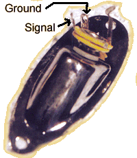 |
| Figure 6 |
| Typical Mono Output Jack |
- Re-install the output jack mounting plate.
- Grin smugly when your bandmates ask you if you put humbuckers in your guitar!
Why a 400V Capacitor?
I've had a few people ask why I specify a 400V capacitor when guitar circuits usually only have a few millivolts on them. The reason is simple, that capacitor is what stands between you (via the grounded strings) and your amplifier. Some vintage tube amps could fail such that they put a potentially lethal DC voltage on the "ground" side of the jack. This type of failure is extremely rare, but why take the chance? The 400V capacitor won't break down like a 35V capacitor would in the admittedly extremely unusual case where you might plug into a "killer" amp. A 250V capacitor is also acceptable as it will probably stand up to 300V or so for at least several seconds. Note that the OEMs don't seem all that worried, most guitars have the strings grounded directly without any isolation. On most guitars, the jack is a non-insulating type which means that the jack plate will be directly connected to the negative side of the jack even after this modification. Metal control knobs may also still be directly connected to the negative side of the jack even with the isolation capacitor in place. Finally, even with the capacitor, a high DC potential failure will give you a nasty "bite" while the capacitor charges – but the capacitor serves to limit the duration and severity of the shock.
You can omit the capacitor entirely (replacing it with a piece of wire) if you're confident you'll never plug into a malfunctioning vintage amp and if you check the house wiring religiously everywhere you play.
Note that the .33uf capacitor recommended here is really intended for protection from DC from a malfunctioning vintage amp. It will only provide minimal protection (though more than most stock guitars provide) from an AC shock caused by improper house wiring. See the very important article on electrical shock.
The .33uf designation is not critical. You could easily get away with a 0.47 or 0.22uf capacitor. The larger the value the better, up to a point (except that larger values will provide less protection from AC shock). If your control cavity is tighter than normal, you might want to go with a 0.1uf 400V because it will be physically smaller. I wouldn't go much lower than that though or you will start suffering noise.
You can also isolate only the bridge and strings by tying the shield ground directly to the signal ground, but isolating the bridge ground wire from the shield by an 0.1uf 450V capacitor. That capacitor will be much smaller and furthermore it can be mounted in the bottom of the body cavity. This method provides a little better protection from AC shock (still not foolproof) via the strings. However, if you use metal knobs on the pots they will not be isolated. Also, the metal shaft on the switch and all the pickguard mounting screws will not be isolated either. Still, this method provides good isolation for the bridge and strings, good noise performance, ease of construction, and it's still safer than most factory guitars. You can see pictures of this technique from when I prototyped the S-Tastic™ circuit for three-pickup guitars.
More Photographs!
January 2008 - I've had a lot of people write to thank me for the instructions over the years. Ryan Byrd put together a PowerPoint™ presentation of
the process. It's heavy on photographs so it's about 6 meg but it's worth the download if you're nervous about doing this yourself. If you get an error
that says you can't open password locked files then you probably have PPT files associated with a full PowerPoint file editor. In that case, download the
file and then open it specifically with the PowerPoint viewer. The file is here. Thanks Ryan!
I Can't Do This!
I would urge you not to perform the above modification if you really aren't comfortable soldering and poking around in the guts of your guitar. The modification really isn't difficult, though. If you're uncertain, you might want to simply remove the pickguard of your guitar and look at the controls and wiring while refering to these instructions – often seeing the actual circuit in front of you makes a world of difference.
Help, the Noise Got Worse!
Most people manage to complete this modification without any difficulty but I do get the occasional panic e-mail. By far the most common mistake people seem to make is accidentally reversing the leads at the jack. When you do this, the guitar will actually get noisier when you touch the strings! Probably the second most common mistake is having a bit of shielding touch part of the audio circuit when the pickguard is reinstalled. This can be a real pain to track down because symptoms vary depending on what part of the circuit is getting shorted and of course the problem goes away as soon as you remove the pickguard to work on it!
My Guitar Still Hums!
No shielding is 100% effective if you're using single-coil pickups. Most people, however, find that following these instructions results in a significant improvement. If you are using single-coil pickups and don't notice much improvement after this modification then it is likely that you've not followed all the steps properly or have inadvertently got a bit of shielding shorting out after reinstalling the pickguard, etc.
Don't overlook the fact that you may have subconsciously cranked up the gain on your amp! We guitarists love saturation and many of us have kind of become conditioned to turn up the gain until the hum becomes objectionable, then turn it back a smidgen.
Another thing to consider is that your amplifier and guitar cord may be contributing to the noise problem. Always plug the amp into a properly grounded power outlet and use a guitar cord with a tightly woven shield braid. Also, always use the shortest guitar cord that you can – if your style includes bouncin' and flouncin' all over the stage then you should spring for a wireless system!
You may need to shield the pickup coils themselves with copper tape. This is especially true if you have hot "overwound" pickups or a very high action (so that the pickups are high in the pickguard), or if you want to play at "way huge" gain levels. Be advised, though, that wrapping the coils with copper will alter the tone – typically you will lose some of the high frequency bite (remember that many tele players remove the factory-equipped metal covers from their neck pickups). This is why I don't routinely recommend wrapping the coils even though it is by far the most effective shielding.
If your guitar was already pretty quiet for a single-coil guitar then the guitar and/or the pickup coils may have already been shielded. A few manufacturers are beginning to wise up and some late model guitars are pretty well shielded. The star-grounding presented here is important more for protection against white noise and radio interference than 60hz hum. If your guitar came from the factory with foil on the back of the pickguard and a heavy layer of shielding paint in the body cavity then following these instructions for the star grounding is probably only going to give you a barely perceptible reduction in hum. A few pickups come already shielded with copper foil. That is the most effective shielding and these instructions, while not doing any harm, will make less difference in hum with such pickups. It should be noted though that even some humbucker equipped guitars will buzz around flourescent lights and such – thorough shielding and grounding as described here does help significantly in those cases even when there is little or no noise coming from the pickups themselves.
|