Low Impedance FX Loop Circuit for Tube Amps
7/09/2008
|
While designing my latest amp (the "Nickel Blues™" - will be written up in full later) I wanted to add an effects loop / line out that would be
low impedance so it could drive long signal lines and so on. So, instead of using a cathode follower to drive the tone stack, I decided to use the
cathode follower to drive the FX send directly so the high impedance of the tone stack would not limit the performance of the FX send. Along the way
I had a couple of other ideas I thought were kind of cool - here's what I ended up with (after the obligatory dire warnings).
 |
 |
CAUTION! Working on tube amplifiers can be extremely dangerous!
Do not attempt this project unless you have been trained to work safely with high voltages. This
project works with AC line voltages and with DC voltages approaching 350 volts - either of which is easily lethal!
Even if you do not get shocked an improperly
modified amplifier can cause a fire that burns down your home.
If it sounds like I'm trying to scare you it's because I am. This project is intended only for
those who are qualified to accomplish it safely. For the rest of you, the best amp in the world isn't worth
killing yourself over!
Use at your own risk!
| |
|
 |
| Low Impedance Tube FX Loop / Line Out |
This circuit should work in most any amp where you can find an insertion point where the signal level is between two and about twenty or thirty volts
peak-to-peak and where a signal of around four volts peak-to-peak is adequate to drive the next stage (or where you will be using the FX loop only with
devices that will supply a strong enough return signal).
By-the-way, there is nothing earth-shattering here - this is all based on prior art (tubes have been around a long time now and there is very little
that isn't at least derived from a handful of pretty common circuits) - but, I explicitly
give permission for others to use this circuit or derivations thereof in their designs, including in commercial designs.
What I don't give anyone permission to do is to claim it is theirs and patent it, as one well known manufacturer routinely does with the work of others.
The company in question routinely patents prior art published in tube manuals and magazines from fifty years ago.
First, those pesky LEDs deserve some mention - what are they doing in a tube amp? Well, in the first amp I used this circuit in the FX loop was following the
second preamp stage and tone stack and the signal at that point could approach twenty volts peak-to-peak or possibly higher even after the insertion
loss of the tone stack. That is well above the specification for a line-level signal and theoretically could damage some line level equipment.
So, those pesky LEDs serve to clamp the signal to +/- about two volts (depending on the diodes used). They serve a secondary purpose in that LEDs tend to
clip more smoothly than other diodes so in some configurations these act like a fairly smooth built-in distortion pedal (more on this later).
The FX send and receive are on the same jack (a 1/4" "stereo" or "TRS" jack). I can't claim credit for this bit of cleverness as I've seen it on
some commercial amps where the goal was obviously to save panel space and/or the cost of a jack. In this case, it works out rather neatly with those
aforementioned LEDs. In short, this "loop" operates in any of five modes depending on whether you use a stereo or mono plug and on how you wire the
plug.
- When nothing is plugged into the jack then the signal from the "DRIVE" control goes directly to the next stage of the amp. The cathode follower
and the limiting LEDs are not in the path and have no effect on the signal.
- If a mono plug is used then the "line out" is on the tip of the jack and the plug clamps the "return" signal to ground, disabling the power amp.
If the amp has a safety resistor across the output transformer secondary you can probably operate the amp safely without a speaker since the input to
the power amp section is clamped to ground. I.e. you can use the amp as a preamp to feed another device, and the LEDs clamp the line-out signal
to a safe level (though it will sound terrible if you turn the "DRIVE" control too high with a strong preamp signal).
- A stereo plug with tip and ring terminals both used (separately). The tip is the "FX SEND" and the ring is "FX RETURN." This is a "normal"
FX loop but with the diodes added to limit the output signal level.
- A stereo plug with only the ring terminal used - the preamp is bypassed and the amp can be used as a power amp fed by some other device.
Depending on the gain following the FX return (or "Line In" if you prefer) this might work well for people who want to feed a POD or other modeller
directly to the power amp.
- A stereo plug with the tip and ring terminals connected (with or without any connection to some other circuit) - this puts the cathode follower and
clamping LEDs into the signal path for the amp - effectively making the cathode follower and LEDs a built-in distortion circuit.
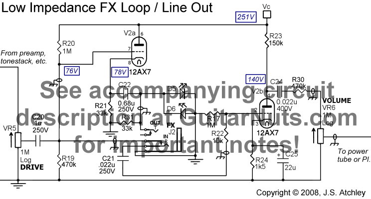
Here are some notes that might be useful as you adapt this circuit to your own amplifier design:
- Resistors R19 and R20 are a simple voltage divider that establish the DC operating point for the cathode follower. Values aren't critical
but you want a DC operating point at least ten volts higher than your highest anticipated peak signal from the DRIVE control.
- Capacitors C20 and C21 block the DC operating point established by R19 and R20 from the rest of the circuit.
- R31 provides a termination for the (possibly clipped) line out signal. It isn't strictly necessary but should be used (and mounted on J2) to
reduce noise radiation inside the chassis if the signal lead to the jack is longer than a couple of inches.
- D5 and D6 are the LEDs and function as described above. They may be omitted if the signal from the DRIVE control is never anticipated to be
more than about six volts peak-to-peak and if the "distortion pedal" functionality is not desired. Typical standard brightness red LEDs will
clip at around +/- 1.5 volts and fairly smoothly - i.e. the signal becomes a square wave with rounded corners. Different wavelength LEDs have
different forward voltage drops so experiment with two different colors for assymetrical clipping.
- R30 is optional. The amp I prototyped this circuit in had wayyyyy too much signal going to the SE power tube grid so I put R30 in to
give the VOLUME pot a more useful range. Note that with R30 in place you can place a 47p or 100p capacitor across the volume pot to tame any
harshness in the preamp.
- The 150k plate resistor (R23) results in very high gain. Very high-quality, low-noise metal film resistors are strongly recommended throughout. Oh,
why the emphasis on gain considering the need for R30 above? Mostly because I really like the way a 12AX7 stage biased exactly this way (150k
plate, 1.5k cathode) sounds as the input stage of an amp, and when the loop is in use or the amp is being used as a stand-alone power amp this is
effectively the input stage. For my personal tastes, the 150k/1.5k input stage is a perfect compromise of good clean
headroom with sweet overdrive and it has lots of gain to kick the next stage in the pants. Bias colder and you get more headroom but when the
stage is driven by a strong signal it becomes harsher. Bias warmer and you get very smooth overdrive but too little clean headroom (important
because the input stage usually precedes any control pots).
- The blue numbers in the boxes are the actual DC voltages measured from the prototype amp - your mileage may vary.
|
