|
This amplifier is the culmination of a bit over two years of planning, designing, simulating (SPICE), dreaming, ordering
parts, and, finally, busting knuckles and sniffing solder fumes. The project started as a quest to build a low-powered amp (15 watts or less)
with all the features of a big amp, and then some. It's intended to be run guts-out into an attenuator and as such is heavily over-engineered
in critical areas. The output transformer, for example, is a 40-watt output transformer which runs cool even when the amp is dimed.
| Features Include: |
| 2 X EL84 Output | Top Quality Low-Noise Components |
| Two Footswitched Channels | Pre-FX Volumes on Each Channel |
| Post-FX Master Volume | Presence Control on Each Channel |
| Switching Via Ground Steering Using Silent, Reliable FETs |
| Well-filtered DC on the Preamp Filaments |
I'm building three of these, two for a friend in Missouri and one for myself. I powered up the first one last night
(17 February, 2007). To my complete astonishment it worked almost flawlessly right off the bat. This is an extremely complex
and high-gain amp and I expected to spend a week or so troubleshooting "issues." The only issue was a problem between the post FX master
volume and, I suspect, the large coupling capacitor on the output of the FX send buffer. I added a resistor to the top of the volume pot
which cleared that up right away.
I'd like to thank all the guys hanging out on the forum over at ax84.com. Some of the
success of this amp has to be credited to a couple of guys over there who I am smarter for just having "rubbed elbows" with - they know
who they are. I'd also like to credit Joe V. at amplates.com for the face plate,
Paul Ruby for the cab, and Mike, the Kombo King for
the chassis. Also thanks to Paul Ruby for the idea to use zener diodes to prevent the bias on the power tubes from being driven too
negative when heavily overdriving the power section (search the AX84.com forum for more info).
The rhythm channel is gorgeous and will do everything from a clean Fender bassman to a cranked plexi with the inputs
strapped. The lead channel is just sick with gain - if you can manage the fret noise it should do just about anything imaginable. One
thing that surprised me though is how well the lead channel does even with overdriven open chords. Many amps turn to mush but on the Nitro
each string
is still pretty clearly defined even at crushing gain. I'd like to snap my suspenders and claim some specialized knowledge and esoteric
build techniques that caused this ("Yeah, we balance the capacitance of the shielded wire against the inductance of the wirewound resistors
in the power filter to achieve that patented sound..."). Unfortunately, I haven't the slightest idea why this amp doesn't mush out
chords the way some do - I guess I just got lucky. I'll post clips when I have a chance to record some (or better, when I get someone else
to record some - the world should not be subjected to my playing unless absolutely necessary). In the mean time, here are a few pictures
of the first build.
|


Yes, Virginia, there are sixteen knobs on that thing...
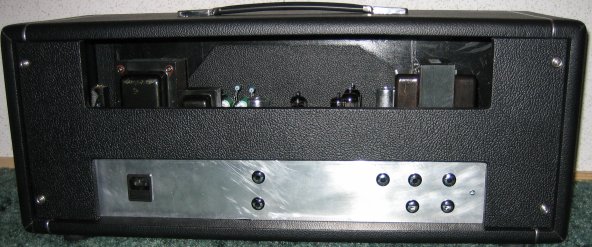
I'm too cheap to buy a back panel so it's time to get the Dymo™ out.
(By-the-way, the scratches only really show up in the flash.)

Note the bi-i-i-i-ig Heyboer output transformer.
The small turret board is the DC supply for the preamp tube filaments.
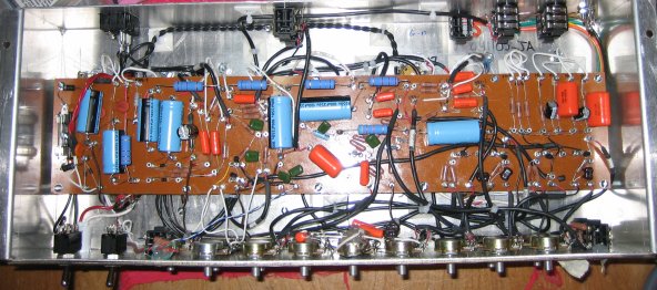
Note liberal use of shielded wire - tedious but worth it - no squeals here.
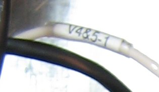
Here's a tip for tagging wires that originate from someplace inaccessible after the turret board is installed. Use your
computer to print some self-adhesive labels in a very small font. Cut them out and wrap them tightly around the wires. Cut them long
enough to wrap completely around the wire at least twice, apply them starting at the blank end and the roll them around so the print is on top
and the label is stuck to itself instead of just the wire. Finally, shrink some
clear heat-shrink tubing over them to protect them and hold them in place. This works well even with wires that are quite thin -
most of the unshielded wires in this amp are AWG-20 with thin teflon insulation. Of course, you can also buy printable heat shrink but
it is expensive and the last I was aware (1994) required a special printer.
|
