The Nickel Blues™ - a Homebrew High-Gain, 5-Watt Tube Amplifier
Updated 12 Oct, 2008
|
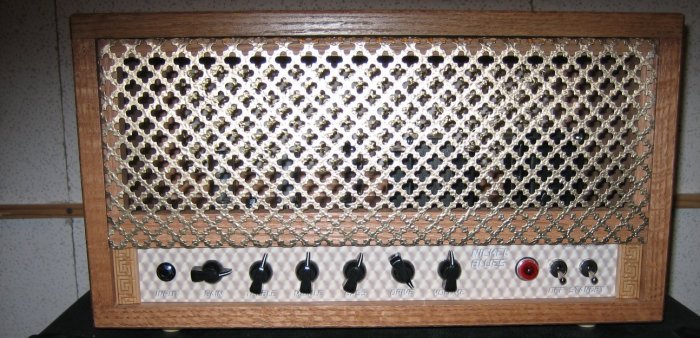
The Completed Prototype
This oak cabinet was made by a friend of a friend because every time I make something
of wood it looks strangely similar to the lopsided birdhouse I made in the third grade.
|
|
|
So, you ask, "why yet another single-ended 5-watt tube amplifier?" (I considered naming the amp YASE-Five but settled
on Nickel Blues, instead.) With a number of commercial and home-brew single-ended designs readily available that is certainly a valid question.
The short answer is that I've yet to find a design that completely satisfies me.
Among the commercial offerings the Blackheart Little Giant comes closest to meeting my needs and were I looking for a
low-gain amp I would modify and tweak a Little Giant rather than building from scratch. In fact, I actually own four of these amps, all modified,
including a better output transformer in one case. You can find an article on modifying the Little Giant elsewhere on this site.
Of the popular DIY designs the High Octane over at AX84.com
is a nice high-gain design but suffers (in my opinion, of
course) from a lack of bottom end "grunt" and seems prone to oscillation if one is not very careful with lead dress and such. To be fair, I haven't
built one and am basing my opinion of the amp on the dozens of clips I've heard. Also, I don't mean to imply in any way that it's a bad design –
many people have successfully built High Octanes and love them. Some people like Fords, some prefer Chevys.
|
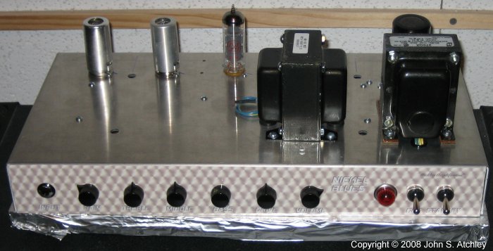
The Prototype Sans Cab
The prototype was built in a High Octane / P1EX pre-punched chassis from
Doberman because I detest
drilling a chassis. While waiting for the cab I set the amp on a piece of plywood covered with foil to shield the bottom from electrical
noise while testing the amp. Ugly but effective.
|
|
|
I set out to design an amplifier that would be similar to a Little Giant but with additional gain, a low-impedance
effects loop, and with emphasis on the ability to get some good low and low-mid "chunk" when desired but without completely sacrificing "sparkle"
on the high end. The design I came up with is actually superficially similar to an AX84 High Octane (there are only so many ways you can arrange
four triodes and a power tube, after all). The overall gain of the Nickel Blues is probably a smidgen higher than that of a High Octane in spite
of its lossier tone stack. The additional low-end is obtained by using larger filter capacitors, a massively over-spec'd output transformer, and
by different voicing in the coupling circuits.
The Nickel Blues features a very warmly biased second stage that is designed to saturate early and smoothly. I've found
that you can get about 90% or 95% of "cranked amp tone" even at apartment levels by biasing one or more preamp stages very warmly. If you first
hear this amp with the volume low and the first gain control dimed you think, "hmmm, that sounds better than some off-the-shelf tube amps do cranked"
– it is only when you then dime the volume control that you realize how much better it can be with the output stage being fully driven.
|
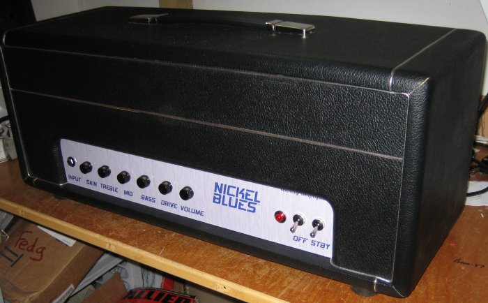
Number Two Completed
I already had a pair of oversize (19-1/2 X 8 X 3-1/2) aluminum chassis made for me by
the Kombo King and matching Marshall style cabs from Paul Ruby so
the next two amps are going into those.
|
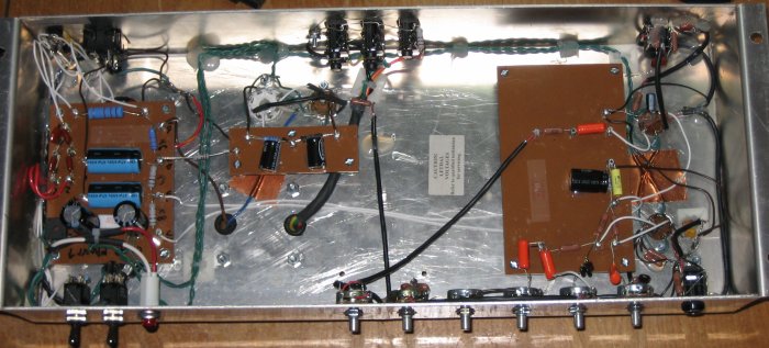
The Guts of Number Two
There is a lot to be said for working in an oversize chassis – especially when your
near vision is getting steadily worse.
|
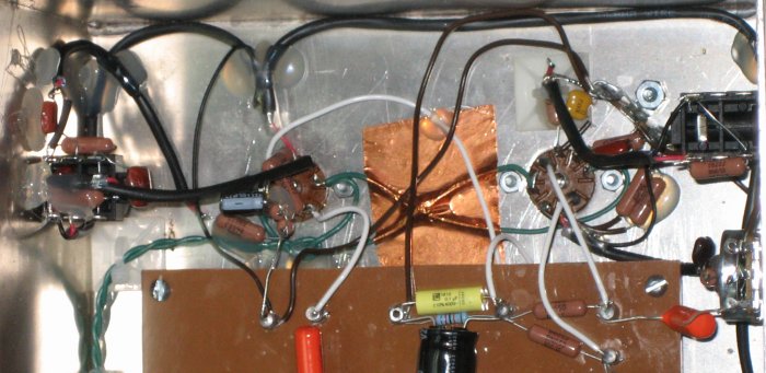
Close up of Point-to-Point
Even with tons of room available I tend to obsess over lead lengths. There are five
resistors and a cap on the V2 socket; three resistors, two LEDs, and two caps on J2, etc. Building this tight makes for quiet amps
but is not recommended for beginners or the weak of heart – replacing any of those components would be a major undertaking.
If you're going to build something this way don't skimp on component quality and derate everything by at least 100%!
The shielding tape over the filament leads is completely unnecessary – especially since
the filaments are well-filtered DC. I use the tape because it's got a very aggressive adhesive that doesn't seem to weaken with age
and heat. (I didn't think of tacking the wiring down with hot glue until I was further into the build).
|
|
Theory of Operation
|
 |
 |
CAUTION! Working on tube amplifiers can be extremely dangerous!
Do not attempt this project unless you have been trained to work safely with high voltages. This
project works with AC line voltages and with DC voltages approaching 400 volts - either of which is easily lethal!
Even if you do not get shocked an improperly
built amplifier can cause a fire that burns down your home.
If it sounds like I'm trying to scare you it's because I am. This project is intended only for
those who are qualified to accomplish it safely. For the rest of you, the best amp in the world isn't worth
killing yourself over!
Use at your own risk!
Should you choose to build an amplifier you do so at your own risk. Neither GuitarNuts nor
John Atchley shall be liable for damages resulting directly or indirectly from this article regardless
of whether or not the build was performed completely in accordance with these notes.
If you are not certain that you understand exactly what is necessary after reading this article and the
accompanying pictures and schematic, that is a very good sign that you are not qualified to perform the
modification!
| |
|
|
|
Throughout this section I make frequent comparisons to the AX84 High Octane amplifier. This isn't to criticize that design,
nor to illustrate how the Nickel Blues is "better" than the High Octane, or anything of the sort. I make the comparisons simply because many
in the DIY community are already familiar with the High Octane, so understanding how this design differs from that one will make it easier for
these folks to evaluate whether they want to consider building a Nickel Blues or perhaps modify a Nickel Blues or High Octane to tailor an
amplifier to something in between that meets their needs more completely than either of those designs.
This description begins at the input to the amp and proceeds stage-by-stage to the output section. This is followed by some
brief notes about the power supply and filament supply. Experienced techs and engineers will find parts of this description hilariously simplified
but that is intentional. Experienced folks can understand the amplifier from the schematic alone. Those who need a description of the theory of
operation probably would not be able to follow a more thorough treatment.
Input and First Gain Stage:
- The input jack is wired like that on almost any amp. A switching jack is used to silence the amp when nothing is plugged in.
- R9 provides a ground reference for the grid of V1a. Placing R9 on the jack side of the grid stopper (R10) eliminates the
slight (about 7%) signal loss that occurs on designs where the grid reference resistor is connected at the junction of the grid stopper and the grid.
- The somewhat unusual plate resistor (R11 - 150k) and cathode resistor (R12 1k5) combination provides slightly more gain (about
2db) than a 100k plate resistor but that's not the main reason why I chose it. I have found that I really like a 12AX7 biased this way for the
first stage of an amp because it provides an ideal (to my ears) compromise between clean headroom and saturation. This only comes into play when
you use a pedal or active pickups to push that first stage hard, but it makes the amp very "pedal friendly." I've found that a first stage biased
more warmly doesn't leave enough clean head room while one biased colder is harsh when overdriven. At least, that's the story my ears tell me and
they're sticking to it.
- This input stage does have one drawback, it is slightly more prone to leakage and thermal noise (hiss) and this is magnified by
the fact that it is the first stage in a fairly high gain preamp. Using low-noise components is essential for the first stage, at least, of this
amp. I used an 0.68u film cap for the cathode bypass (C15) in spite of my stated desire to emphasize bass response because using a noisy
electrolytic can be problematic here. V1a and its associated components are not the place to cut corners. If you don't want a hiss-o-matic,
use a good tube socket, top-quality metal film resistors and film and silver-mica caps, clean all of your contacts and leads really well and make
sure you have excellent metal-to-metal contact before soldering the components. Also, avoid using tubes selected for extra high gain in the V1
position – they are almost invariably much noisier than lower-gain 12AX7s.
- As with any high gain amp if you do a lot of volume swells with the guitar's volume control you may want to add a series
capacitor (.047u or larger film) between the input jack and R10 to eliminate crackling because of a changing bias on the grid. If you do add a
series capacitor, make sure that you do not get it between R9 and the grid (i.e. don't break the grid DC ground reference provided by R9).
Using a 68k resistor for R10 helps minimize crackling so you may not need a series capacitor even if you do volume swells – see the discussion of
R33 in the next section.
- The 68k grid stopper resistor (R10) and the 39-47p capacitor (C32) in parallel with the small capacitance of the grid of V1a
forms a low-pass filter that kills any tendency for the amp to oscillate. As you might surmise from the out-of-sequence component number, C32
was added when debugging and tweaking the prototype.
|
|
I've seen a lot of discussion by knowledgeable builders on the AX84.com forum, guys and gals whose
experience I respect and admire, claiming that a grid stopper resistor is unnecessary and, if used at all, should be as small as possible to avoid
gain loss and high-end loss. I can only go by my own experience and have to disagree. As for omitting the grid stopper entirely I had one
commercial amp that did not have a grid stopper – it picked up a radio station very noticeably when my friend used it in a church about a quarter
mile from the transmitting antenna. Also, going from no grid stopper to a 10k grid stopper makes a barely measurable difference (about one tenth
of a decibel) in gain across the entire audio spectrum. So, at the very least I strongly recommend at least a 10k grid stopper on any amp.
I started with a 10k grid stopper on the the Nickel Blues as that has proven adequate on my other
designs, including a two-channel plexi-ish amp that was a very tight build. However, the Nickel Blues topography puts the very large signal
(hundreds of volts) at the primary of the output transformer in phase with the input on the grid of the first input stage (this topography is
shared by the High Octane, by-the-way). I've built higher gain amps that did not squeal but this is the first time I've used a single-ended
topography that put the output signal in phase with the input. I was surprised (though probably shouldn't have been if I'd only given it more
thought) when the prototype whistled in spite of careful lead dress and extensive use of shielded wire. While scoping the prototype I discovered
that when the amp broke into oscillation the oscillation was appearing on the grid of V1a. I reviewed all of the commercial high-gain amplifier
schematics I could lay hands on and found that pretty much all of them use a 33k to 68k grid stopper and a small (39 or 47p) capacitor across the
first grid.
So, I went to a 68k grid stopper. This stopped the amp's tendency to whistle the theme song from
Mayberry RFD when dimed and tickled even by something as small as a bit of noise, but there were still problems. One of the best tests for whether
something is going wonky in an amplifier is to play a high open harmonic (seventh or nineteenth fret harmonic on high e-string, for example) and listen
carefully while muting all of the other strings. If the note begins normally but pinches off suddenly, or if a raspy overtone gradually seeps in
to trash the delicate harmonic even though the volume is not increasing due to feedback, that high harmonic is probably "tickling" some part of the
amp into oscillation. Typically, a strong ultrasonic oscillation will pinch the note off completely and suddenly while a weaker oscillation will
"beat" against the note and gradually overcome it. The Nickel Blues still had a slight tendency to do the latter with all controls dimed, so I
added C32.
The following picture shows a plot from SPICE of the first stage gain response in three configurations.

Frequency Response as Calculated by SPICE
As you can see, C32 really only affects frequencies above 5k, and even then it is only down about 1dB
at 15 kilohertz (compared to the 68k resistor alone). The 68k resistor and C32 together are down less than 3db at 10k and down less than 5db at
15k compared to a 10k resistor alone. That is audible but not very significant in the guitar spectrum. If anything, my ears prefer the sound of
the bottom trace. Of course, if you really like screaming, almost painful highs, or if you've lost most of your high-frequency hearing after
playing in front of cranked stacks for 30 years, your mileage may vary! Myself, I'll gladly accept this slight decrease in piercing highs for a
stable amp.
|
|
|
Gain Control and Coupling to 2nd Stage:
- C14 is the coupling capacitor that isolates the high DC potential at the plate of V1a from the components that follow. Good-quality capacitors
that are not prone to leakage or breaking down are essential for the coupling capacitors of all stages. I use "Orange Drops" but any good-quality
film capacitors (rated 400V or better) are fine.
- VR1 is a 1M audio pot as used in just about every tube amp design you'll find. The value is by no means critical but such a high resistance
avoids loading the signal and leaves lots of "possibilities" for shaping the frequency response with other components.
- C16, R33, and R13 form a network that reduces the signal by about 33% but serves two important functions. First R33 significantly reduces any
tendency for the amp to "pump" or crackle when the gain control is changed. Without R33 the grid reference resistance for V1b varies from 0 ohms
(short to ground) to around 500k as the gain is turned up. With R33 the grid reference resistance changes from around 250k to around 595k.
- Second, R33 and C16 even out the frequency response through the second stage as the gain control is moved from near zero to maximum.
Without R33 the second stage attenuates almost none of the highs when the control is dimed and drastically cuts the highs when the gain control is
reduced to very low levels (because almost the full 1 megohm of the pot is effectively in series with the grid capacitance). R33 alters this by
reducing the ratio of minimum to maximum resistance in series with the grid capacitance from 1:1000 or higher to something more like 1:3.
C16 prevents the overall high frequency loss from being too severe.
- Some amps use a "bright" cap across the high and wiper terminals of the gain pot. I'm not a real fan of this approach because you can end up
actually making the response brighter as the gain control is turned down very low – and typically when I'm playing clean I want all the bass I can
get, I only want to cut bass to reduce “splattery” intermodulation distortion when overdriving. The circuit used in the Nickel Blues (and the High
Octane) still allows for some cutting of highs (relative boosting of bass) as the amp is cleaned up.
- Note that C16, R33, and R13 are similar in value to the equivalent components in the High Octane. This circuit cuts a little less signal (33%
vs. 50%) and emphasizes the "bright" component a little less than does that in the High Octane.
- SW3, if used, defeats the "bright" circuit when the switch is open. R33 remains in circuit to prevent pumping and crackling. The amp will be
pretty dark with the switch open, so I'm not sure how useful it would be.
- A more useful approach might be to wire the switch as shown for SW4 – "boost" would allow one to boost the overall gain and further emphasize
the highs if the switch is closed when the gain pot is dimed. If the switch is closed with the gain control low the amp will be quite dark.
- Note that I haven't built an amp with either SW3 or SW4, and probably won't. My gut feeling is that the amp will be very dark with SW3
open and I simply don't need the gain boost that would happen with SW4 closed. When I boost gain I prefer to use a pedal to push the first stage
harder.
Second Gain Stage:
- V1b is biased very warmly and saturates early, providing very smooth preamp overdrive as discussed in the first part of this document. The
small cathode resistor (R15, 560 ohms) causes a fairly small bias on the grid and that in turn increases current at idle, dropping the plate
voltage to about half the supply voltage. When a signal is applied to the grid the tube goes into saturation (maximum conduction) much earlier
than cutoff (minimum conduction). Triodes enter saturation gradually (especially when fed from a high-impedance source) and thus the signal
compresses smoothly at the bottom of the output waveform. By contrast a tube goes into cutoff quite suddenly, leaving very sharp square-edged
distortion similar to that of a typical transistor circuit.
- As mentioned in the introduction, you can get about 90% to 95% of "cranked amp tone" from warmly biased preamp stages like this one. In
situations where volume has to be severely limited I have found that I prefer the tone from a warm preamp stage to the tone from a power amp
heavily "strangled" by any of the attenuators I've tried.
- Ordinarily a warm stage like this has one major drawback, it seriously limits clean headroom. In this design we have stages with good
headroom before and after this saturation stage and individual gain controls so when headroom is desired we can easily reduce the level of the
signal going through this stage while maintaining adequate overall gain to fully drive the power tube.
Tone Stack:
- This is a typical tone stack as used in many preamps patterned after the "Marshall style" (including the High Octane) with the major exception
that it is not driven by a cathode follower. What difference does that make? A cathode follower lowers the source impedance driving the stack from
around 40k or 50k to around 2k or less. Lack of a cathode follower means that this stack is considerably "lossier" than a stack driven by a cathode
follower. Overall, across the guitar spectrum this stack will average about 6db more signal loss than the almost identical stack in the High
Octane.
- So, why did I choose not to use a cathode follower to drive the stack? For two reasons. First, recall that one of the design goals was to
have a good low impedance FX loop. The only practical place to put an FX loop in this amp is after the tone stack and that is not by any means a
low-impedance point in the circuit, even if the stack was driven by a cathode follower. So, I used the cathode follower to drive the FX loop
directly – ensuring an output impedance around 2k.
- Second, remember that another design goal was to have good low-end "grunt" when desired. The tone stack actually cuts less bass (in relation
to the overall spectrum) when driven by a high impedance than when driven by a low impedance. Essentially, the bass control becomes more
effective. Another way of looking at this is that the tone stack cuts about the same amount of bass when driven by a low or high impedance, but
that the stack cuts as much as 6db more from the top two thirds of the guitar spectrum when driven by a high impedance.
Cathode Follower and Effects Loop:
- The effects loop is unique to this design - so far as I know, anyway. It's awfully difficult to claim originality when people have been doing
interesting things with tubes for seventy years! Though at least one commercial amp manufacturer seems determined to patent every circuit he digs
out of 50 year old magazines and tube manuals!
- J2 is a switching TRS jack that provides both the send and return for the FX loop. When nothing is plugged into J2 the cathode follower is
not in the audio path, the full signal from the gain control (VR5) goes directly through the switched ring terminal and to the final preamp gain
stage (V2b). When a stereo plug is inserted, the FX send (buffered by the cathode follower V2a) is on the tip and the return is on the ring.
If a mono plug is inserted the buffered send is on the tip and the return is grounded – in this configuration it is safe to operate the amplifier
as a preamp with no speaker attached due to the grounded input and the safety resistor (R29) across the output transformer.
- LEDs D5 and D6 protect external equipment by clamping the sent signal to about +/- 1.5 volts (approximately, depending on the forward voltage
drop across the LEDs which varies with color and type). LEDs also clamp fairly smoothly (they are used as clippers in some distortion pedals).
So, whenever the FX loop is in use you have a built in overdrive pedal, sort of.
- R20 and R19 form a voltage divider to pull the cathode follower well above ground to ensure that the signal is not clipped hard by the cathode
follower. C20 and C21 prevent this bias voltage from affecting the rest of the preamp. See the schematic for additional notes regarding the
FX circuit.
FX Recovery / Final Preamp Stage / Master Volume:
- V2b is biased just like the first stage – see that section for what that means. This is done because when the FX loop is used (or if the FX
return is used as a power-amp input from some other device being used as a preamp, such as a POD or what have you) I wanted it to overdrive the
same way the first stage does, for the same reasons. The only difference is that here noise is not as critical because this is not the first of
three gain stages, but the last. Therefore, I used a 22uf electrolytic for the cathode bypass capacitor (C25) for good bass response.
- R30 cuts down some unneeded gain that can be troublesome when the FX loop is not being used. Without it the volume control is very sensitive
and it is easy to push the power amp into blocking distortion. C23 acts with R30 to form a low pass filter that trims high frequencies and "rounds
off" sharp edges from the preamp distortion, making the overall amp smoother (this was mentioned in the section on the gain control and
second-stage coupling). This is an area where you can easily tailor the amp to suit your tastes – from no capacitor at all up to about 220p, maybe
even 470p for those who like really, really smooth output and don't mind sacrificing bite to get it. I found that 220p took away too much bite
(and I like fairly dark amps). I ended up using two 220p caps in series for 110p.
- R25 is the grid resistor for the output power tube. A more typical value here is 5.6k but when I was scoping the prototype I noticed that the
power section became unstable and did weird things when the volume control (VR6) was turned all the way down (shorting the wiper to ground).
This happened regardless of any other control settings. I checked the volume pot with an ohmmeter (after allowing the circuit to drain, of course)
and found that the instability occurred when the total resistance between the EL84 grid and ground fell below about 8k. Changing to a 10k
resistor solved the problem. Why? I dunno – 'cuz it's tubes?
Power Amplifier:
- The PA can use either an EL84 or a 6V6 tube. I used separate cathode bias resistors because typically a 6V6 requires quite a bit more bias
voltage than an EL84. Keep in mind that this design is really optimized for best performance as a "lead" EL84 amplifier. An EL84 is biased just
about perfectly and is also at its "sweetest" plate voltage. I've tested two builds with a variety of EL84 tubes and the plate dissipation has
varied between 11.8 and 12.1 watts with mains voltage at 119VAC. Screen dissipation is about 1.25 watts.
- The 6V6 works fine for clean and lightly crunched material but it takes a lot more signal on the grid to overdrive a 6V6 than is required by
an EL84. With a 6V6 in place the additional current drawn pulls down the supply voltage through the amp so there is even less voltage available
to drive the grid. Also, the 6V6 is biased just a little cold (about 13W plate dissipation, 14W is the rated dissipation for a 6V6). You can
overdrive a 6V6 hard but it just doesn't sound as good as an EL84 in this circuit.
- One could probably reduce the cathode resistor on the 6V6 to about 300 or 310 ohms for a little warmer bias, but this would draw even more
current and lower the voltages through the amp even further. It would also increase the power dissipated by R4 to somewhere near its rated 5
watts (it's dissipating about 3.6W with a 6V6 as is).
- A better solution if one intends to use the amp mostly as a 6V6 amp might be to lower R4 to around 800 ohms and then increase the cathode
resistor for the EL84 as needed to keep an EL84 at it's 12W bias point. This may, however, make the EL84 sound a bit strident or stiff
(I'm not crazy about the sound of EL84s run at unusually high voltages and low currents). This will also reduce the effectiveness of the power
supply filtering and may result in slightly more hum.
- The bottom line is that it is very difficult, though not impossible, to design an amplifier that will be a really good EL84 amp and a really
good 6V6 amp. Doing that requires more complexity – such as switching R4 when the tubes are swapped so that each tube is running at its optimum
voltage and current. It's very easy to compromise and build an amp that is a so-so EL84 amp and a so-so 6V6 amp, but I was not willing to go there
so this design is a really good EL84 amp and only a fair 6V6 amp. If I really wanted to use the amp for "lead" with both the EL84 and 6V6 I would
probably add a switch to change the value of R4 from 1.2k to about 800 or 900 ohms when switching to the 6V6.
- Finally, note the use of rather large cathode bypass capacitors in the power amp. Many amps use as little as 22uf or 33uf here and if you
just run the math that would seem to be adequate. However, such small capacitors can be "pumped up" by unheard subsonic frequencies, changing
the bias point and driving the amp "colder." One of the changes I recommend to almost any cathode-biased amp is to increase this bypass cap to
at least 330uf.
High Voltage Power Supply:
- Power supply filtering is critical in a single-ended amp and also critical for good bass response. When built as shown and if the grounding
notes on the schematic are followed hum is basically non-existent and bass response is superb. On the prototype, built in a16X8X2 aluminum
P1X/High Octane chassis from Doberman, there was just a hint of hum detectable under the white noise of the high gain preamp with everything dimed.
The next two amps were built on a larger 19-1/2X8X3 aluminum chassis and I can't hear any hum under the white noise at all with the controls dimed.
However, I attribute the difference in hum to the better filament supply in the subsequent amps (see below), rather than the chassis size.
Obviously, your mileage may vary depending on how careful you are with lead dress, shielded wiring, etc.
Filament Power Supply:
- I highly recommend DC power to the filaments on this amplifier but inadequately filtered DC can create more noise than AC filaments due to the
sharp switching transients on the rectifier diodes. About 10,000uf of capacitance is required per amp of current to bring ripple voltage down to
about a volt. Such a large electrolytic capacitor does a very poor job of filtering very fast transients such as those from the rectifier diodes
so it is very important to bypass the electrolytic cap with a poly cap of around 0.1uf (this value is not critical).
- NOTE: If you do not adequately filter the output of the bridge rectifier you will have a very annoying hum or buzz – annoying because it is
at 120hz instead of 60hz and that puts it well within the guitar spectrum. The resulting noise will "beat" against some of the notes you play and
the amp will sound terrible!
- The amount of capacitance is a balancing act between adequate filtration and avoiding overloading the power transformer due to capacitive
loading on the filament winding. 10,000uf is about as much capacitive loading as I'm willing to apply to a winding being used at about 50% of
it's rated capacity (as is the case with 1.4 amps on the 3A winding of a Hammond 270DX). I built the prototype with a single 10,000uf capacitor
and it worked okay, with about 1.2p-p volts ripple on the filament supply to all tubes. Then, I had a better idea...
- On subsequent amps I used a simple pi filter with two 4700u caps and a 1R1 2 watt (actually, 5 watt was what I had handy) resistor. The power
tube filament is supplied from the first stage of the filter and the preamp tubes are supplied by the last stage. This resulted in slightly
higher ripple on the power tube filament but reduced ripple on the preamp filaments to about 0.7p-p. This also reduced the capacitive loading on
the transformer. The transformer doesn't run uncomfortably warm on either amplifier but the difference in transformer temperature between the two
amps after idling in standby for a long time is detectable.
- This also reduces the filament voltage to the preamp tubes to right at the low edge of the nominal range (5.8VDC measured with mains voltage
at 119VAC). This shouldn't be a problem unless you frequently play through brownouts – in which case you might get EVH's "brown sound!"
|
Schematic
If you "save a copy" you will be able to view it full-screen using Adobe reader...
|
|
|
|
|
