Improving the Crate™ VC-508 5-Watt Tube Amp
Updated 3 August, 2005
|
Update 5 August, 2005 - I finally took time to get the last of the harshness
out of this amp and to install a jack for an external speaker. I've never liked the way the so-called tone control
works on this amp - it basically just adds harsh overtones at anything except either extreme. I also wanted to improve
the bass response of the amp a little. As it turns out, adding one jumper wire accomplishes both tasks. The
jumper from the wiper to one end of the tone pot (shown on the latest version of the schematic) cuts some highs and makes
the tone control work like a typical tone control - i.e. turn it CW for treble, CCW to cut treble.
I have good news and better news. The good news is that I just returned from spending a week with a friend in Missouri
so I have some new clips of the latest version of this amp. The better news is that he plays a lot better than I do
and I can finally replace the ear-punishing clips of my playing!
The amp is played through three cabs - the built in speaker, a custom 1 X 12 sealed cab loaded with an 8 ohm Celestion
Vintage 30 (made in China but made a few years ago before quality control apparently became non-existent), and an
identical cab loaded with a lightly doped Weber VST 12" 8 ohm alnico Silver Bell. The custom 1 X 12
cabinets are very large - approximately the same interior volume as a Mesa Boogie Dual Rectifier 2 X 12! They are
made by Grady Butler in Springfield, MO and sound absolutely awesome.
| Clips |
|---|
These clips were recorded using the VC-508 modified as described here and a standard (MIM) Strat with Bartolini
XV3 "Vintage" stacked humbuckers without a preamp (these are very low output pickups - lower even than most
single coils). The guitar is modified with my "double-barrel" switching but Brian used mostly the stock Strat
positions for these clips. Absolutely no effects were used and no post processing was done (other than compression to
MP3 format. The clips were first recorded using a Yamaha 4-track tape machine with DBX and high transport speed, then
the clips were played and recorded via sound card. EQ was flat during recording and playback. Later, I cut
the long clips into reasonable sized chunks using Audacity and converted them to MP3s using CDeX. Again, no post
processing was done, not even normalization of the levels during MP3 compression.
These were all recorded at "living room volume." We were actually recording in one upstairs bedroom of Brian's
townhouse while his day-sleeping neighbor slept in the adjacent unit. I checked the volume in the other upstairs
bedroom with both bedroom doors closed and the sound coming through the wall was a low background level. These
clips are all recorded using nothing but preamp overdrive - the power tube was nowhere near being overdriven!
Note that the samples of the internal speaker are of a Weber 8" alnico speaker. The somewhat "metallic" tone in
these clips was not at all apparent live (both Brian and I were surprised by how good the bass response of the internal
speaker was). Initially I thought this metallic sound might be due to "hammering" the tubes that are located so close
to the speaker but that should have been audible live. The more I think about it I think this metallic sound may come from close mic'ing the internal speaker
with the perforated metal grill over it - that's about the only explanation I can come up with for the marked difference
between the mic'ed sound and live sound. |
| Cab | Gain | Tone | Broadband | Dialup |
| INT | 7 |
4 |
Clip 1 (1M) |
Clip 1 (400k) |
| Clip 2 (1M) |
Clip 2 (400k) |
| Clip 3 (450k) |
Clip 3 (165k) |
| 9 |
Clip 4 (1.2M) |
Clip 4 (411k) |
| V30 | 7 |
4 |
Clip 5 (960k) |
Clip 5 (350k) |
| Clip 6 (500k) |
Clip 6 (190k) |
| Clip 7 (1.6M) (blues) |
Clip 7 (630k) (blues) |
| 9 |
Clip 8 (840k) |
Clip 8 (294k) |
| Clip 9 (1.6M) |
Clip 9 (575k) |
| Clip 10 (692k) |
Clip 10 (261k) |
| Weber | 7 |
4 |
Clip 11 (1.6M) (blues) |
Clip 11 (650k) (blues) |
| 10 |
Clip 12 (940k) |
Clip 12 (325k) |
| Clip 13 (490k) |
Clip 13 (187k) |
| Clip 14 (1.8M) |
Clip 14 (654k) |
| 8 |
0 |
Clip 15 (876k) |
Clip 15 (347k) |
| 4 |
Clip 16 (689k) |
Clip 16 (255k) |
| Clip 17 (1M) |
Clip 17 (378k) |
| 9 |
10 |
Clip 18 (778k) |
Clip 18 (267k) |
| 10 |
5 |
Clip 19 (859k) |
Clip 19 (294k) |
| Clip 20 (1.6M) |
Clip 20 (575k) |
| The above clips are a mixture of rock and blues. Those actually marked "blues" (clips 7 and 11)
are of special note both because they illustrate very well how the modified VC-508 responds to picking dynamics and
because they are similar material at the same amp settings making possible a direct comparison between the Weber and
Vintage 30 speakers in identical cabinets.
|
|
|
Update 20 November, 2004 - On the 1st of November 2004 I posted here a mention
that after the NOS 12AT7 I'd originally used in this modification gave it's all during a road trip that I was unable
to find another 12AT7 that had as high a gain, and that lower gain 12AT7s were giving unsatisfactory results because
of the solid state preamp going into clipping before the tube goes into saturation. I have since fixed that
with another simple modification. The new change calls for replacing the preamp cathode resistors (R10 and R15)
with 560 ohm resistors, or, if you don't feel like pulling the circuit board, wiring a 1k resistor across each of them (the parallel
combination of 1.5k and 1k gives 600 ohms, close enough for our purposes.) This change makes the preamp go into
saturation earlier. The result is a preamp that works well with either a typical 12AT7 or even with a 12AX7,
because this circuit generally won't push even a 12AX7 over into cutoff with such a low resistance on the cathode.
Note that if you don't want to do the whole modification shown here, just doing the above alone should
make the amp sound much better, especially if you drop in a 12AT7 tube at the same time.
Also, I don't think I ever made mention of it here, but several months ago I discovered that
when the preamp is driven hard C9 may introduce very harsh distortion - so I removed C9.
The new modified schematic includes both of the changes above.
|
|
 |
 |
CAUTION! Working on tube amplifiers can be extremely dangerous!
Do not attempt this project unless you have been trained to work safely with high voltages. This
project works with AC line voltages and with DC voltages approaching 400 volts - either of which is easily lethal!
Even if you do not get shocked while working on the modification, you or someone
else can be electrocuted later when simply using the amp if the modification is not performed properly. Even if no one is ever injured, an improperly
modified amplifier can cause a fire that burns down your home.
If it sounds like I'm trying to scare you it's because I am. This project is intended only for
those who are qualified to accomplish it safely. For the rest of you, the best amp in the world isn't worth
killing yourself over!
Use at your own risk!
This modification will void the manufacturer's warranty. Should you choose to perform this
modification you do so at your own risk. Neither the manufacturer of the amplifier, GuitarNuts, nor
John Atchley shall be liable for damages resulting directly or indirectly from this modification regardless
of whether or not the modification was performed completely in accordance with these notes.
If you are not certain that you understand exactly what is necessary after reading this article and the
accompanying pictures and schematic, that is a very good sign that you are not qualified to perform the
modification!
| |
|
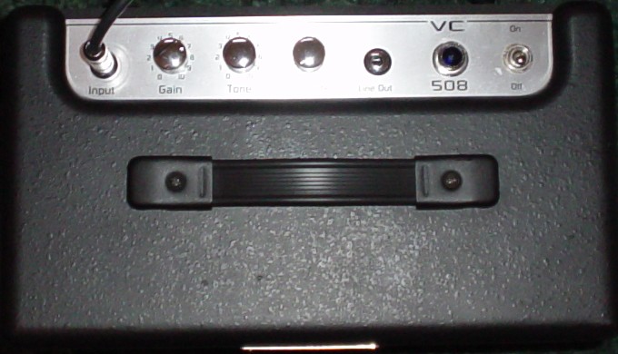
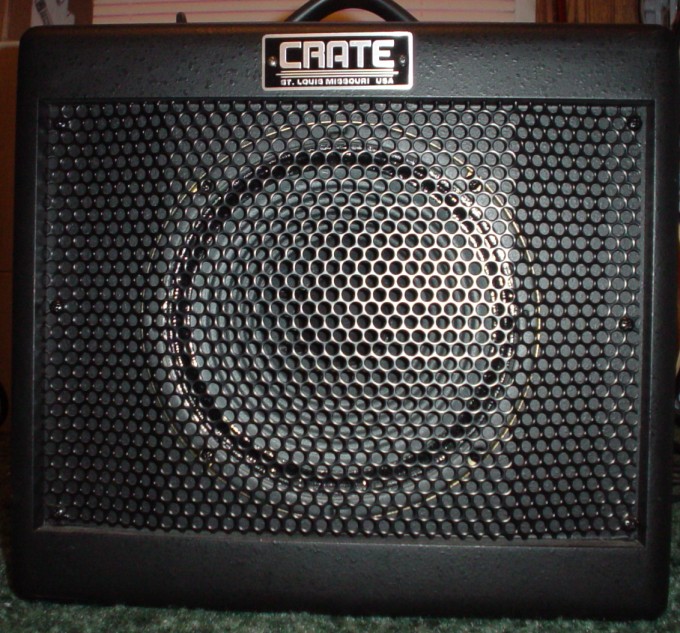
The Crate VC-508 guitar amplifier is a small "inexpensive" single-ended 5-Watt tube amplifier. It uses a
single EL84 and a single 12AX7. It is not an "all-tube" amplifier, there is a TL072 op amp up front to
provide the initial gain stages. This solid-state front end and the spatter-painted instead of
Tolexed cab are obvious attempts to keep manufacturing costs to a minimum. However, that doesn't necessarily
make them bad. The painted cab looks okay and is easy to touch up and the solid-state front end is actually a
very good idea that I wish we'd see more of. Op-amps make sense in the first couple of gain
stages where their low noise, freedom from filament hum, and low output impedance make them ideal for initially
boosting the signal well above the noise floor and for driving lossy tone stacks.
That said, I frankly wasn't expecting much from the VC-508 because it seems very much to have been designed
by bean counters. Why did I even buy one, you ask? Because I felt that the amp might be a good starting
point for making a much better sounding tube amplifier at reasonable cost. If you look about, you can pick
up a used VC-508 for less than the cost of parts to build an AX84 P1, for example. Recently, I've been
experimenting with tube preamp circuits using a Spice simulator and those experiments seemed to indicate that
almost all production amps these days are using preamp circuits that are actually biased for 12AT7 tubes, not
12AX7 tubes. I figured that a used VC-508 would be a cheap way to test my theory.
While I wasn't expecting much from the VC-508, I have to say that the reality was far worse than anything I'd
imagined possible. I can honestly report that I have never heard a worse-sounding tube amp. The only
way I can think to describe the overdrive is that it resembled the sound a table saw makes when it hits a nail. In fact,
my Danelectro Nifty-Fifty™ solid state amp breaks up more smoothly than my VC-508 did. I imagine that it's
possible that I got a bad sample, especialy since this amp was used (though like new, not a nick and still
had the hang tags on it). However, I doubt it, because when I went through the amp with scope and voltmeter
all of the readings were very close to the annotations on the factory schematic.
The oscilloscope quickly revealed the problem. Actually, to be honest the Spice simulations I ran before I
even received the amp revealed the problem, the 'scope just confirmed it. The first tube stage was being driven into very harsh clipping well
before the power tube was even getting close to compressing. Almost all tube amps using 12AX7s in the preamp
are actually set up for 12AT7s. When you put a 12AX7 in the circuit the stage will overdrive at the top
of the output waveform with very harsh clipping. Put a 12AT7 in that same circuit and the voltage level
on the plate changes and nine times out of ten the overdrive will begin at the bottom of the waveform and be
smoothly rounded instead of harshly clipped at the top of the waveform.
As I said, that's common to almost all 12AX7 preamps and one of the reasons that preamp overdrive has such a bad
reputation. Take a circuit where no matter what combination of gain and volume you use the preamp is clipping
before the power section starts overdriving and you might as well have a solid-state amp - and a bad one at that.
That was exactly the case in the VC-508 I was working with.
The first thing I did was replace the 12AX7 with a 12AT7 and then test the amp again. (By-the-way, the tubes
on this amp are hidden behind the chassis, between the chassis and the speaker baffle, you pretty much have to
remove the chassis from the cab to change a tube!) Just this simple change made a drastic improvement in the
sound (that's not unusual, many amps benefit from having one or more preamp tubes replaced with a 12AT7).
Most of the painful "sawing-nails" sound was gone, but with the lower gain preamp tube it was now impossible to
overdrive the output tube well because of the strange design of the "volume" control.
This amp has a line out, which is cleverly wired using a TRS jack such that if you use a 1/4" mono plug it is a
line out and the power amp is muted, but you can wire a stereo plug for a complete effects loop, sending on the
tip and receiving on the ring. Somebody made two fairly poor decisions regarding this jack, though.
First, they decided that the volume control must affect the line out (instead of being content with the gain and tone
controls), and second, they decided that the line
out should be limited to an extremely weak signal, well below what is typical for a "line" level signal.
As a consequence of those design decisions, the "volume" pot is located between the two tube preamp stages,
instead of between the last preamp stage and the power tube. This means that the relationship between
the second tube stage of the preamp and the power amp can't be changed, severly limiting the tonal usefulness.
Also, the "line out" really can't be used well with devices, such as a Digitech Studio S200, that expect a true
line-level input. Fortunately, both problems are fairly easy to fix.
My second modification, which in all honesty I'd planned before I even received the amp, was to move the volume
control from its oddball location to a more useful position between the last preamp stage and the power tube.
Unfortunately, this amp uses those silly little plastic PCB mount pots and I couldn't find a 250k pot that would
fit in place of the 10k pot. What I ended up doing was adding a full-sized pot to the bottom of the chassis,
so it must be adjusted from the back of the amp. That's a minor inconvenience and it may have been for the
best, as if I'd used the original pot location I'd have had to string wires carrying fairly high level signals
over to the preamp section.
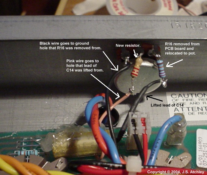
I found that I was able to make the modification without cutting any traces on the PCB. First, I lifted the
ground leg of the existing volume pot and put a 56k resistor between it and ground. That made the existing
volume pot pretty useless, but raised the available drive to the second tube stage of the preamp. Now, the second
tube stage of the preamp will overdrive just slightly before the first tube stage, and they will both overdrive smoothly at
the bottom of the output waveform instead of clipping harshly at the top (because we're using a 12AT7 tube).
Of course, this makes it absolutely essential to attenuate the signal between the last preamp stage and the
power amp or we will be driving the power amp tube ridiculously hard. Again, by lifting a leg of the
coupling capacitor and removing and relocating the power tube grid resistor I was able to wire in the new
master volume pot without cutting any circuit traces.
The total parts list for this modification? A 12AT7 tube, a 56K 1/2W resistor, a 2.2K 1/2W resistor, a
.022u PIO capacitor (because I had one I wanted to try, so I replaced the coupling cap, you may re-use the
existing .047u poly cap), and a 250k audio taper potentiometer.
I can't honestly say that it's now the best sounding amp I've ever heard. However,
the modified amp not only sounds better, it honestly sounds about as good as I think an amp can be made to sound
through an inexpensive 8-inch speaker in a particle-board open-back cab (an extension cab with a better speaker
is planned next). One can now get anything from clean through light crunch through heavy distortion out of
either the preamp, or the power amp, or both. Even at much higher preamp distortion levels than I am
inclined to use the tone remains quite warm. As presently modified it's a keeper, with a decent AlNico speaker I think it
could become a "go to" amp.
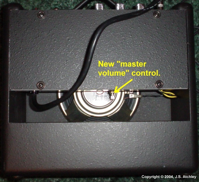
Location of New Full-Sized "Master Volume" Potentiometer
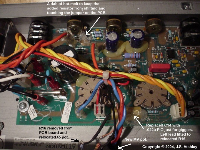
A View of the Modified Guts.
Another View of the Modified Guts.
The large (1.4Mb) PDF schematic of the modification is available here.
Be sure you read the large number of notes and warnings on the schematic!
Update - 4/15/2004
I ordered a Signature 8 ("Sig8") alnico speaker from
Weber VST and installed it. This was the alnico speaker recommended by
Ted Weber after I explained to him the sound I was looking for. I had been leaning towards the more expensive
Vintage 8, but it turns out it has a much larger magnet and will not clear the tubes in the VC-508. The
difference with the Weber speaker was noticeable with the master
volume all the way up and the amp cranked to about 4 and better on the gain. The Weber was smoother
while maintaining good definition and a tight (for an 8" speaker) bottom end. This is not to say that the
Celestion ceramic speaker installed by the factory is not a good speaker. In fact, at very low ("baby sleeping
in next room") settings of the master volume the difference between the speakers was subtle enough that I had to
listen closely to an "AB" tape to hear the difference.
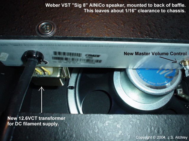
The Weber alnico speaker also offers another advantage – the magnet is narrow enough that it should be
possible to mount the speaker to the back of the speaker baffle instead of the front (I didn't notice this until
I had the speaker in, I'm probably going to change it soon). I've never cared much
for speakers mounted to the front of a baffle with no cushioning between the steel basket and the baffle, as is
done with the VC-508, because it's just asking for rattles to develop if the amp is played at high volumes a lot.
Also, there is less support for the speaker cone rim than with the speaker "properly" mounted behind the baffle.
I also added some cooling holes to the rear cover. Almost all combos tend to trap heat and with its unusual
placement of the tubes the VC-508 seems worse than most in that regard. Obviously, if you do this you need
to make sure not to leave the amp unattended around small children who are given to inserting paper clips or what
have you into the holes. While the amp still gets quite warm, as all combos do, it runs considerably cooler
which could significantly prolong its life.
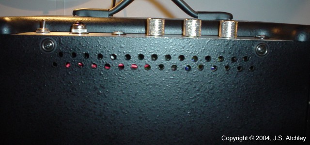
A few minutes with the drill press gives cooler operation.
(Obviously, remove the cover before drilling it!)
By-the-way, if you need touch-up paint Krylon interior/exterior "semi-flat" black paint
is a near-perfect match.
My next modification is going to be to reduce hum. This amp hums fairly loudly, even compared to other tube
amps. To be fair, it's not very noticeable when you're playing. However, it becomes very noticeable as
soon as you close mic it. SE amps are sometimes more prone to hum than PP amps because there is no way to
cancel the filament hum in the output stage. However, this amp has more hum coming from the preamp stage and
that is most likely because the heater filaments are not referenced to anything. Unfortunately, it won't be
possible to reference the filament voltage to the output cathode because the filament supply also drives a pair
of voltage doublers to
develop the +/- seven volts needed for the op-amp. I'll have to give it some thought but if all else fails
I'll build a small DC filament supply and mount it in the bottom of the cab – the amp just has too much potential
to let a little thing like excessive hum ruin it.
Update - 4/17/2004
Well, I burned a little midnight oil last night and built a DC filament supply into the VC-508. The results
were somewhat disappointing. There was a reduction in hum, but the amp still retains enough hum to make close
miking and recording while playing at low amp volumes a no-go. There is simply too much AC wiring run all over
the amp, and it's pretty obvious that space and cost savings were the primary concerns of the circuit board
design. Don't
get me wrong, it's still a great little amp, you just aren't going to be making a lot of high-quality recordings
with it. Of course, I guess you can't really expect a "studio amp" for the price this thing sells for...
|
"Later that day..." – In reviewing the pictures for this article I noticed that many of the AC carrying
wire pairs were not twisted very tightly. I went back in and twisted them and moved them around a bit and
got rid of more of the hum. Most of the remaining hum, which is pretty faint and present regardless of gain
and volume positions, is probably from coupling between the transformers and ripple on the HV supply. There isn't
much to be done about the coupling on such a tiny chassis, and I'm not sure I can find room for additional filter
caps. Besides, the hum is now reduced to the point that hiss has become the more apparent nuisance.
I put a scope on it and most of this "white noise" appears to be coming from the solid-state preamp. I think I'm going
to try replacing the op-amp chip with a lower-noise version and replacing the capacitors in this section with
better quality low-leakage caps. The factory caps look like tantalum caps and if they are that is about
the worst possible choice for a low-level, high-gain audio circuit. The hiss is only noticeable when the
gain and volume controls are both turned up, but any noise is too much noise...
|
I also remounted the Weber speaker so that it is mounted to the back of the baffle in the traditional manner.
There is just enough room to do so...
Things are getting tight...
This morning I was playing and realized that a resonance that had been present around E to F# (on the D string)
is gone. This resonance was just enough to make the tone sound just a little "off" when played as part of
a double-stop. In fact, it was subtle enough that I'm not sure whether the resonance disappeared immediately after
I first installed the Weber speaker or only after I remounted it to the back of the baffle. In any case, the
F# sure sounds better now.
The following are some more pictures of the DC filament modification, though I'm not really recommending it –
it's an awful lot of work for only a little improvement.
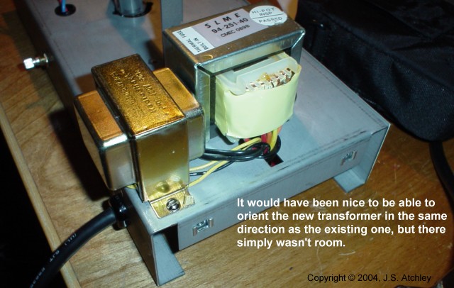
The new 12.6VCT transformer for the DC supply.
Upon further reflection, orienting the new transformer with the existing power transformer probably wouldn't make much
difference anyway. There appears to be little, if any, magnetic coupling between the PT and OT, I'm pretty
sure most of the hum is due to the AC wiring being run willy-nilly through the amp.
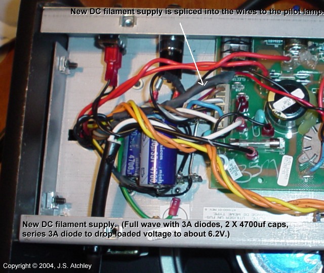
The half-wave rectifier and filter.
This new filament supply uses a 12.6VCT 1.2A transformer, three 3 amp diodes, and two 4700uf 35V capacitors.
It is a basic full-wave rectifier, the third diode is used to reduce the loaded output from about 6.9V to 6.2V –
this amp already runs quite hot and I figured I'd rather have the filaments on the cool side of acceptable than on
the hot side. There is about 1V pk-pk ripple on the supply, which is okay for a filament supply.
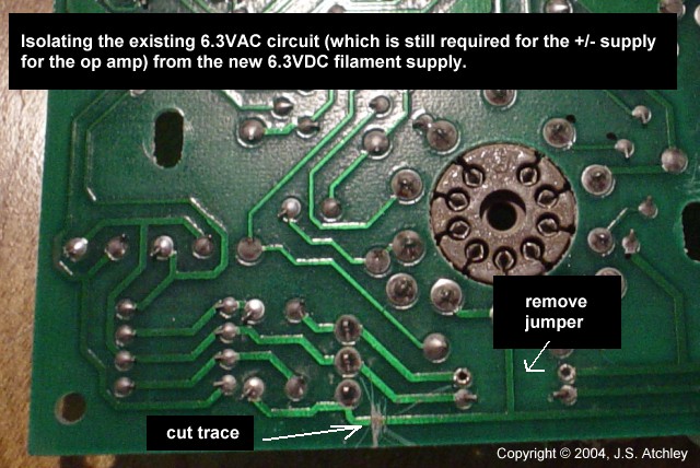
Only two changes (one a cut trace) needed on the PCB.
|
